DCS analog input problem

M

Thread Starter

mahmoud fawzy

Hi everybody,

Please I need your advice for the following problem.

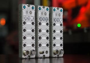
We have 4 Analog output signals 4- 20 mA sent by analog output card model ADAM 4024 has 4 channels connected to yokogawa DCS CENTUM VP analog input card model AAI143 (DCS is passive) .

When we try to connect the fuses and knife bridges of marshaling cabinet during the loop check and starting simulating mA on one channel of ADAM card, the other channels change also. the values of mA not match with what we simulate and the values we get in DCS (ranges are same in DCS and the field).


We make the following tests
1- We disconnect all the cables that connect between ADAM card and DCS except one channel (for example channel no 1). we measure the mA in series by multimeter we get 4 mA and this a correct values. we try to connect the wires of the other channels; we notice the value of mA increases to 8 mA. also when we connect just one wire positive or negative the value of mA change too, and this happened for all other channels when we repeat the same test on the remaining 3 channels.

2- we bring mA loop calibrator. we use it to measure mA in one channel. And connect multimeter in series with resistance box adjusted on 250 Ω. We notice that the two channels don't affect each other even if we increase the resistance until 1 kΩ.

Please, help me to find interpretation for the reason that make mismatching between the DCS and the ADAM card. and what we do to make this connection work.

Thank you
 
Classic ground loop symptoms

When you connect a battery powered simulator, it's floating with respect to earth. It reads or provides a floating source that works OK.

But when you connect a device whose ultimate (-)/common reference is an earth ground at a potential different than the potential at the device being connected to, then you have a ground loop.

Are the AOs from the Adam grounded? Or, is the DC power supply (-) to the Adam grounded? If so, lift the ground and see if the problem disappears.
 
M

mahmoud fawzy

Thank you for reply,

our power supply model is MOXA DR-4524 feeds 24 VdC to ADAM card , Negative side was grounded, we remove the power supply ground, But nothing change.

We made another test..!!

We move one channel to another yokogawa analog input card. We found it works only if one channel from ADAM connected to one analog input card in DCS.

But until now i didn't know what the reason for why the four channels of ADAM not working together at the same analog input card without effecting each other?

Thank you for interesting
 
The symptoms you're seeing are a classic example of exceeding the common mode limitation of the analog input. But the specs say both the AO module and the DCS AI use isolation. This is not typical for devices using isolation.

A Yokogawa spec sheet states "allowable common mode voltage ±1 V or less" for a different card, the non-isolated AAB141 input card. A low level ±1 V of common mode tolerance would explain the effect you're seeing. But the AAB143 is supposed to have isolated inputs, not non-isolated inputs.

Have you actually looked at the input card model number? Is it really an AAB143 (with isolation)?

On the Adam 4024, there are three GND terminals; 4, 13, and 24; two on one terminal strip, one on the other. One of the three is for (-)/common for the DC power supply, the other two should not be connected to anything. Is that the case?
 
M

mahmoud fawzy

Hi David ,

yes, sure yokogawa card model is AAI143-H Analog Input Module (4 to 20 mA, 16-channel, Isolated,With HART Communication).

On the other side The connection of ADAM-4024 is
power supply + on (R)+VS
power supply - on (B) GND 13
DATA + on (Y) DATA+
DATA - on (Y) DATA-
Channel 1 on IOUT 0+,IOUT 0-
Channel 2 on IOUT 1+,IOUT 1-
Channel 3 on IOUT 2+,IOUT 2-
Channel 4 on IOUT 3+,IOUT 3-

so every thing suppose to work!!

i wonder if we move every channel to different cards "one channel/AI card," this will affect on other AI signals specially that have their power from the field side?

thank you
 
Given the nature of what you've reported thus far, I can't predict what will happen if you connect a single AO to a single DCS card. It does not sound at all like expected operation of isolated devices.

Three other thoughts:

1) Any junction boxes/marshalling terminals in between the Adam and the DCS I/O? Somewhere where terminals could be jumpered or shorted to other terminals, one of which is a ground or screen/shield?

2) Has someone connected a screen/shield to a (-) terminal?

3) Are you positive whatever method (jumpers or wiring, whatever) is used to make the DCS AI a passive AI has been done for EACH channel? You're not taking some guy's word for this, you've seen it yourself? So that an active Adam analog output is not bucking an active DCS analog input?
 
M

mahmoud fawzy

Hi, David

>Given the nature of what you've reported thus far, I can't predict
> what will happen if you connect a single AO to a single DCS card.
> It does not sound at all like expected operation of isolated devices.

i agree with you. the operation of that isolated cards not like the isolated one, but i don't know exactly which side should blame for this problem?

> 1)Any junction boxes/marshaling terminals in between the Adam and
> the DCS I/O? Somewhere where terminals could be jumpered or shorted
to other
> terminals, one of which is a ground or screen/shield?

no junction boxes/marshalling terminals in between the Adam and DCS I/O. the connection for every signal with 2 wire and the shield one side connected to the ground of DCS.

another test i made. i connected 2 signals to DCS at the same AI card, but this time i connected ground to (-) terminals. i found one signal went to 12 mA (the correct value should be 4 mA) and the other went to over 20 mA (the correct value should be 4 mA) so this also didn't work.

> 2) Has someone connected a screen/shield to a (-) terminal?

no connection for these signals screen/shield and (-) terminal. also no connection between (-) terminal and ground in DCS or in Adam.

> 3) Are you positive whatever method (jumpers or wiring, whatever) is
> used to make the DCS AI a passive AI has been done for EACH channel?
> You're not taking some guy's word for this, you've seen it yourself?
> So that an active Adam analog output is not bucking an active DCS analog input?

i'm sure that all the 4 AI channels in DCS AI card are passive, but i wonder if there are any configurations of ADAM-4024 to make it passive. may be this can solve the problem?

thank you for interesting
 
M

mahmoud fawzy

Hi David,

I got one information form yokogawa training material that last number in AI/AO cards refers to type of isolation. for example:

AAI141 last number is 1 so the card not isolated

AAI143 last number is 3 so the card is common isolated "the channels have multiplexer and share the same photo-coupler"

AAI135 last number is 5 so the card isolated per channel "every channel have photo-coupler"

may be this explain the behavior of AAI143 with ADAM card, because AAI143 card channel not isolated "share some electronic components before photo-coupler"?

thanks
 
Mr. Fawzy,

That's a very interesting observation. A common for all channels is what allows common mode voltage to affect the signals like you've seen.

Most likely, the multiplexor is not individual relays, but solid state with a common for all channels. Having a common connection between channels is the factor in common mode - common mode on one signal becomes common mode for all channels on the same module through the common connection. Adding a signal with common mode adds to the existing common mode and the result is offset or driving

By the way, the Adam 4024 spec sheet says, "isolation voltage: 3000Vdc". But that's not really a definition because it doesn't say where the isolation is; between what two points. It could mean from the outside of the case to the inside of the case.

Any plant big enough for a DCS will very likely have a loop isolator or two in the instrument shop. Why don't you run a test on one or two loops with a loop isolator between the Adam and the DCS AI to see if using an isolator provides a useable signal to the DCS AI?

If an isolator solves the problem, then that's a solution.

There's some chance that the Adam is as culpable as the DCS AI given the lack of what is isolated from what. There are other brand Modbus-to-AO modules that advertise "3 way isolation"; power supply-to-network-to-output.

Thanks for the update. If you run a test with loop isolator(s) please let us know the outcome.
 
I just want to comment that this is a great thread to follow. I enjoyed reading the dialog very much. It appears that perhaps these two systems are nearby, perhaps in the same marshalling or control room.

Could there be a ground loop of some sorts forming between the ground points of the power supplies for each system and this somehow interacting with the I/O cards? But I suppose normally the best practice is for control system ground to be kept separate from equipment grounds?

I think the loop isolators is a great suggestion. I can't wait to hear back what the final resolution is on this issue.
 
Top