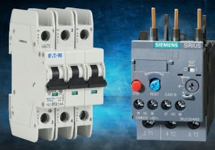
WIKA T32 Temperature transmitter

Q

Thread Starter

QUANGNGUYENVAN

Dear All members of Control.com
I am working on power plant 1200MW, we apply Wika T32 temperature transmitter for BFP winding & bearing temperature (8pcs) but by the trend on DCS we found that sometime temperature drop to -4.2degC and quickly recovers. It happened randomly and repeatedly.

It will trip BFP if the temp > 140degC, -4.2degC is alarm direction of transmitter we set to Lo if we set Hi, the pump will trip frequently. T32 was configured to RTD 3Wire measurement.

First, we doubt to RTD element, but when we change T32 to Rosemount and keep the monitoring for more than 1 week, signal drop is not coming anymore (not intend to blame Wika and glad to rosemount)

I have two question.

1. What condition make the T32 alarm active? (such as loss of the element RTD wiring ....?) Please let me know all conditions that T32 alarm activate.

2. Is the transmitter fail or any setting to solve problem?

Any advice would be highly appreciate.

 
It isn't clear whether only one of 8 points has the drop out problem, or all eight. If all 8 there's some common mode failure associated with all 8.

I'll assume that there was only one point going bad, and the replacement transmitter is using the same DC power supply, wiring and receiver analog input. If the original RTD element is still used with the replacement transmitter then the fault lies in the transmitter or its wiring connections. While a transmitter could have an intermittent open fault, those kinds of devices are quite robust, so I'd suspect the wiring or the sensor element first.

On rare occasions a crimped connector/ferrule will connect intermittently with the wire and cause an open.

One time, (20 years ago) I found a poor connection at the terminal block due to a film, like clear coat or varnish, on the terminal screw/washer. One screw terminal was had a slightly different appearance. Turning the terminal screw with a screwdriver would connect or disconnect the signal as the copper wire rubbed against the washer. Replacing the screw/washer on that terminal gave good contact/good signal even with a mildly loose screw.

If the RTD element was replaced with the replacement transmitter , then the RTD element probably had an internal intermittently bad connection that would open. RTDs are more delicate than thermocouples and if the application involves vibration, this is not an unlikely potential cause.
 
Q

QUANGNGUYENVAN

Dear David
Appreciate your reply. I have totally same idea with you at the beginning when we see this problem. Also sorry for some unclear points. Please find it here

1. There are 4 (total 8 signal per pump, we have 2 pump per unit, plant have 2 unit then we have 4 bfp, all the pump we have same problem. Some signal drop out the pump we change have 4 per 8 signal drop out.) Signals same problem drop out not only one.

2. We change only transmitter not the RTD element.

Any other idea? Also how about the question when the alarm of transmitter triggers?

Thanks
 
>Also how about the question when the alarm of transmitter triggers?

I don't have a clue what temperature alarms your DCS triggers. I'm a temperature guy.

Let me summarize what the situation appears to be at this point.

4 indicated temperature signals fault, drop out at the same moment, and then recover at the same time.

Replacing one transmitter of the four temperature transmitters (with a different brand/model) while still using the original RTD stopped the pattern of random signal faults.

Correct?
I am stumped as to why swapping a single transmitter would inhibit an intermittent, multiple device fault.

More questions:

1) I assumed these temp transmitters are 4-20mA HART, but I have to ask, are they Profibus or Foundation Fieldbus?

2) How long a time does the drop out last? How many data points is the signal at -4? What is the historian's sampling rate?

3) Are there intrinsic safety barriers in these temperature transmitter circuits? passive barriers or powered isolators?

4) Is one side of the loop power supply earth grounded? Are all four transmitters powered by the same power supply?

5) How many of the given 4 channels connect to the same analog input (AI) module?

I find it hard to believe that multiple transmitters with individual RTDs will fault in the same manner at the same time on their own. A common mode failure in individual temp transmitters is hard to imagine.

However, the power supply and the analog inputs are most likely common to all 4 signals, which is major factor in finding a common mode failure.

If it were me, I'd
- check RTDs for an unwanted low resistance connection (due to damage or internal failure) from any RTD wire to the sensor sheath which could cause a ground loop. An RTD should be isolated from ground on all 3 wires
- start experimenting to see what set of conditions

Loss of DC power?
An open circuit in the RTD wiring to the transmitter?
An open circuit in the loop wiring from transmitter to AI?
A drop in power supply voltage?

causes a -4 Deg reading because that's the fault condition that is recorded by the historian.

I can think of 3 potential causes
a) intermittent power supply fault
b) analog input card malfunction - probably a mux
c) intermittent ground loop driving loop current negative due to a recurring intermittent 'event' that causes a ground loop through a grounded power supply
 
Q

QUANGNGUYENVAN

David,

you misunderstanding my writing. Might be my english is not clear enough.

1. I was asking about the transmitter alarm, what conditions it will activated? that option is not setting on the DCS, it was set at the transmitter. If you using the HART communicator connection to transmitter, one option are Alarm, can be set to Hi or Lo some transmitter say Upscal/Downscal. We are seting Lo. Lo =3.75mA or 3.85 mA when transmitter internal alarm or element wiring break/short.

I know that when RTD element wiring break/short alarm option of transmitter will activated and transmitter will output the current Hi/Lo accordingly to it was set Hi/Lo by HART example.
My question is, beside of element wiring break/short any other condition that the alarm condition will be activated?

2. it is not 4 transmitter drop same time and recovery same time. It happened randomly, not the same time please. but BFP-A unit 1 was have 4 transmitter problem per total 8 transmitters.

Replace one of 4 transmitters fault from Wika T32 to Rosemount 248, the RTD element no touch, no change. This signal after 1 week mornitoring is no problem. 3 fault transmitter still randomly drop out (not same time drop out please).

My question is do you guy have any experience with Wika T32 same problem as I meet above, any solution?

Because it happened all the pump; BFP-1A Unit1 4 per 8 transmitters drop out randomly short time then recovery (4 transmitter not same time drop out, and not same time recovery please); BFP-1B unit1 3 per 8 same problem; BFP-2A Unit2 5 per 8 same problem; BFP-2B Unit2 4 per 8 problems

Unit2 already all replace to Rosemount 248 then problem stop. RTD no touch, no change please.

Hope above is clear.

Any experts have any advice??????????
 
The non-periodic nature of the drop-outs is like what the industry experienced 30 years ago when a tech with a walkie-talkie portable radio stood next to, or in close vicinity of, a field transmitter.

When the tech keyed the radio 'on' to transmit, an indicating transmitter would go wild and drive its measurement PV off-scale. Product engineering (the sales guys talked about ferrite beads) seems to have minimized, if not eliminated, that kind of fault. I would think that German engineering would account for radio interference in a field transmitter's design.

But who knows, is there any correlation to the drop-outs you are seeing and whether personnel in the area used portable radios? It would be an easy test to make - go out, key a radio on and see if the control room sees a down-spike.

>My question is, beside of element wiring break/short any other condition that the alarm condition will be activated?

As to what makes a T32 go into failsafe mode, their spec sheet says the T32 does "Self-monitoring" which is defined as "active permanently, e.g. RAM/ROM test, logical program operating checks and validity check". A failure or fault discovered by the internal diagnostics will put the transmitter into failsafe (low output) state. This is typical of modern temperature transmitters, particularly those used in safety systems.

I suppose Wika could have gotten a lot of some bad electrical component that could cause spurious drop-outs under who knows what condition(s). Another major vendor got a lot of bad diodes recently. It can happen.

Hopefully someone with some field experience with multiple T32s will show up and comment, too.
 
Q

QUANGNGUYENVAN

I already found the reason why it is happened to wika Temperature transmitter.
It is not the transmitter fault, but the function/feature design different with Rosemount.

Thank you all.
 
P
Hi,

We have the same problem. How do you fixed it? Did you replace the transmitters?

>I already found the reason why it is happened to wika
>Temperature transmitter.
>It is not the transmitter fault, but the function/feature
>design different with Rosemount.

Thanks.
 
HART temperature transmitters are HART temperature transmitters.

The one thing that might differ is that Rosemount sets its failure mode output low level to 3.9mA, not 3.8mA.

From the Rosemount 644 manual:
"If the sensor temperature is outside the range limits, the transmitter saturates its output to 3.9 mA for standard configuration on the low end (3.8 mA if configured for NAMUR-compliant operation)."

The Rosemount 3144P has the same settings/situation.

But a difference in failure-mode output levels does not explain why multiple transmitters would fail at the same time.

Multiple transmitter might go to fault mode if the common DC power supply could not carry the combined load, or if something else powered by the power supply momentarily loaded the power supply so it would crowbar or droop.

The T32 manual recommends equipotential bonding between the housing ground and the far end of the sensor sheath, "for applications with higher EMC requirements" which translates into not allowing a common mode ground loop to develop. (page 16).

Versions of these transmitters can handle dual sensors and do things like fail-over or alarm on an excessive deviation between readings, but that's not likely a momentary or temporary fault-mode.

The troubleshooting guide on page 36 is clear. There are 4 listed causes for I < 4mA, the fault-low state:

- Process temperature out-of-range (conceivable as a momentary issue)

- sensor burnout or short circuit (unlikely to fix itself after awhile)

- Wrong sensor connection (unlikely if the readings are valid at all)

- Wrong transmitter configuration (covers about everything except a firmware or hardware fault)

If you do solve this, it would help everyone to reply here with an explicit explanation about what you found, because you're seeing how relatively useless a vague explanation is.
 
Top