Analog Input Barrier

H

Thread Starter

HK

What is the purpose of Analog Input Barrier in DCS loop Diagram?
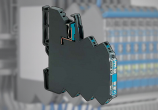
In one example it is shown as P & F module KDF2-STC4 -1 is used.
What is the function of barrier - in other words?
 
I have a spec sheet for a P&F KFD2-STC4-2

That model is a dual channel isolator, providing isolation from one side to the other for two separate 4-20mA field instruments. Is it transparent to HART, meaning that HART is not stripped off/lost going through/across the isolator. It is not an Intrinsic Safety barrier.

Isolators are used to eliminate ground loops caused by differences in ground potentials, which appears as either an signal offset, signal saturation or AI input destruction, depending on the magnitude of the potential difference.

It could be that the KFD2-STC4-1 is a single channel version, but without a model-specific data/spec sheet it's speculation.


P&F has a very good web page;
http://pepperl-fuchs.no/global/en/classid_1824.htm?view=productdetails&prodid=53654

Summary from the datasheet for the KFD2STC4-1 is;
- 1-channel signal conditioner
- 24 V DC supply (Power Rail)
- Input 2-wire and 3-wire SMART transmitters and 2-wire SMART current sources
- Output 0/4 mA ... 20 mA
- Terminal blocks with test sockets
- Up to SIL 2 acc. to IEC 61508

This signal conditioner provides the isolation for non-intrinsically safe applications. The device supplies 2-wire and 3-wire SMART transmitters, and can also be used with 2-wire SMART current sources. It transfers the analog input signal as an isolated current value. Digital signals may be superimposed on the input signal and are transferred bi-directionally.

If the HART communication resistance in the loop is too low, the internal resistance of 250Ω between terminals 8 and 9 can be used. Test sockets for the connection of HART communicators are integrated into the terminals of the device.
 
Top