26MW TURBINE SHEAR PINS BREAKING ISSUE

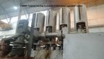
26 MW triveni steam turbine, generator side coupling shear pins broken suddenly, whenever in synch form with another 16 MW AEG turbine. This happened 09 times since 26 MW installation i.e. 03 years before. What are the reasons of coupling shear pins broken?

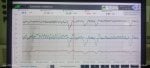
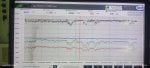
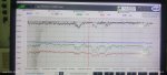
Please find the attached pictures and trends as required.
 

Attachments

bilal.bhatti
1. Do you have a trending chart showing kW, kV, Amps, and Pf for the two paralleled machines, especially when the "disturbance" occurred?
2. Were the coupling failures always associated with the larger machine?
3. Since the failures have stopped can you provide kW, kV, Amps, and Pf, when 3 machines are paralleled?
Regards, Phil Corso
The answer to your queries goes something like this.

1.Attached please find trend of both the machines when disturbance occurred.

2.Yes, failure always occurred with the large machine i.e., 26 MW.

3.Attached please find the trends of all 03 machines in parallel.

Regards.
 

Attachments

Phil will be able to solve this for you.

I am just throwing out a big what if. Mainly for Phil to consider.

I have seen two isoch fight each other. Often the bigger one wins.

Iscoch gen sets do not reject load well. Perhaps the bigger one could win but has weak coupling bolts.

My worthless opinion thinks protective relay/droop/excitation controls need work.

LOL
 
bilal.bhatti...
Thank you for info. My approach will be based on determining Torque-Values for 3-conditions, for the 2-Gen'r case, namely: a) Pre-Disturbance; b) During-Disturbance; and c) Post-Disturbance, for the 2-Gen case !
The 3-Gen Case will also be evaluated!
Three more questions:
1) What is feeder-cable size and length between Gen's and Load bus!
2) Although I can provide a reasonable value of phase Synchronous Impedance, it would simplify the math if you obtained the value directly from the Mfg.
3) Curious-One brings up a good point: Does failure occur during Manual, Auto, or both, Synchronizations?
Regards, Phil Corso
 
"PhilCorso,
bilal.bhatti...
Thank you for info. My approach will be based on determining Torque-Values for 3-conditions, for the 2-Gen'r case, namely: a) Pre-Disturbance; b) During-Disturbance; and c) Post-Disturbance, for the 2-Gen case !
The 3-Gen Case will also be evaluated!
Three more questions:
1) What is feeder-cable size and length between Gen's and Load bus!
2) Although I can provide a reasonable value of phase Synchronous Impedance, it would simplify the math if you obtained the value directly from the Mfg.
3) Curious-One brings up a good point: Does failure occur during Manual, Auto, or both, Synchronizations?
Regards, Phil Corso
[/QUOTE]
 
Hello

Something is a bit messy or not well tuned at your plant...I do not know yet what ..it can be Governor/controller or protection relay also ...

Looks like unit went on undervoltage ..humm best to share protection relay trends /events recording to get better overview of what is going on ..

If no datas from Protection relays ( generator /line ..) I can not add more informations on how to solve that issue...
 
Thank you very much for your comments.
Will share all the desired information's soon after consulting concern Department.
Regards
Hello,

Below please find the reply from my Power Plant Manager.

As you know that Motor creates amperes and then produce certain torque. Like that generator on load produce certain torque on load. In our case no torque recorder installed but we can calculate it.

The maximum torque that the Turbine could produce at the output of gear shaft at 1500 RPM and 100% load (26MW) as per the parameters of prime mover is 165,521 Nm.


a) Pre-Disturbance.

At 15000KW load the value of torque become 95493 Nm.

b) During-Disturbance.

As the trend of load shows a constant load with little bit variation as in our sugar plant and steel plant so the torque value will be same as above 95493.

c) Post-Disturbance, for the 2-Gen case.

Torque values depends on remaining electrical load the 3-Gen Case will also be evaluated.

Same as above.


Three more questions:

1) What is feeder-cable size and length between Gen's and Load bus!

SLD is attached. Pl. Check.

2) Although I can provide a reasonable value of phase Synchronous Impedance, it would simplify the math if you obtained the value directly from the Mfg.

OK, Pl. Provide a reasonable value, if you can.

3) Curious-One brings up a good point:

Does failure occur during Manual, Auto, or both, Synchronizations?

Our Synchronization system is automatic, and failure occurred 09 times in synch form and two times happened running independently.


Regards
M.Bilal Bhatti


Power transmission.jpeg
 
Electric motors convert amperes into torque.

Electric generators convert torque (provided by a prime mover—in this case steam turbines) into amperes.

Wires connect the generator(s) and motor(s). Prime movers actually do the work of the motors, by transmitting torque over the interconnecting wires using amperes as the medium. (It’s like a hydraulic piston performing work using the torque transmitted from a hydraulic motor using hydraulic fluid as the medium.)

I don’t see any cable sizes or lengths on the SLD (Single-Line Diagram).

The description of synchronization is very confusing. The act of connecting a synchronous generator to a grid (of any size or configuration, from a single synchronous generator to hundreds or thousands of synchronous generators) is, usually, called synchronization and involves matching frequency (very nearly equal but not exactly as there must usually be a difference for the synchronization relays to work properly) and voltage (as closely as possible) and phases (though that doesn’t usually happen after the very first synchronization).

Once the incoming synchronous generator is connected to the grid it is then considered to be synchronized to the other generators on the grid, sometimes referred to as as operating in parallel with the other generators on the grid.

If the majority of coupling bolt breakages happen while synchronization is occurring (when the generator is being connected to the grid) the most likely cause is a problem or problems with the synchronization relay scheme OR for some brief period of time after the incoming generator breaker is closed the incoming generator and one or more of the other generators on the grid are operating in Isochronous Speed Control Mode.

There can be some issues with circulating currents—that is best left to PhilCorso, who will no doubt take this discussion off line and it will be of zero benefit to anyone who may read this thread now or in the future.

But, if you and your Plant Manager and the Maintenance Departament Manager are CERTAIN the coupling bolts are the proper ones for the application and the majority of the bolt failures are occurring during the act of synchronization then there is something very, Very, VERY wrong with either the automatic synchronizing relay and/or the synchronization check relay (which is usually required to ensure the generator is not synchronized when it shouldn’t be). Because there can be very high mechanical forces generated when synchronization is attempted when the frequency is not properly matched and/or the voltages are not properly matched. And if this has been happening repeatedly over time I would strongly suggest that the times when it occurred during synchronized operation were the result of serious problems during previous synchronization attempts which weakened the coupling bolts and finally resulted in failure due to some load changes on the system.

The other possibility is that the frequency control system for the plant grid is contributing to the issues because it’s not properly programmed or is being over-ridden by operators or some other control system.

But for properly sized coupling bolts to fail so often requires severe mechanical forces such as would be the result of closing or attempts to close the generator breaker when synchronizing conditions were not correct. Mechanical forces break coupling bolts. And very large mechanical forces can result in a very short period (tenths of a cycle) during problematic synchronization attempts. And if this happens during every synchronization then the coupling bolts are going to experience repeated and sharp high mechanical forces which would eventually result in breakage.

The above is based on the information provided, since we can’t know anything other than what has been provided. It is STRONGLY SUGGESTED that a knowledgeable and experienced person/firm be engaged and brought to site to observe and gather data and review the synchronization relay settings—in particular—and make recommendations for resolving the problem. To be best prepared for this you need to have coupling bolt shear strength information and synchronization relay parameters and a good description of the plant frequency control scheme ready for submission and review.

Best of luck. It would be great if you could write back with the results.

But, remember: Generators convert torque into amperes. Motors convert amperes into torque. Wires are used to send the torque—in the form of amperes—from the generator to the motors.

Tchau!
 
WTF...
No, I didn't go "dark" on bilal.bhatti study. Waiting for info.

Nor did I go "dark" on JSMHarish's project! I'm waiting for his response to my uncovering an error on the "Fault Chart". Didn't you catch it?

Regards, Phil
 
bilal.bhatti

I cannot believe this. I have steered clear of the post because everyone has a data needed and study needed.

Please, if you can synch in manual DO SO.

Adjust your voltage to match the other generator.

Adjust your frequency to ensure your sync scope is stopped and at 12 OClock.

By STOPPED: I mean hold the scope at 12 OClock. No forward and No reverse direction.

This may take some time depending on how sensitive your manual controls are.

Then close the generator breaker.

If you do not break Coupling Bolts, then you KNOW that it is not mechanical.
 
There is another possibility--the generator breaker. If the signal from the automatic synchronizer to the generator breaker isn't coordinated with the breaker closing time the breaker could be closing well outside the best possible window of closure and leading to higher than normal mechanical forces. This would also probably, eventually, cause problems with the breaker and/or it's closing mechanism.

So, if the generator breaker of this 26 MW unit has been having issues OR if the breaker closure signal from the automatic synchronizer isn't properly coordinated with actual time it takes for the breaker to close after receiving the signal to close then this could be the cause of the problem with coupling bolt failures.

And, again, the bolts could be weakened by multiple out-of-synch closures and not always break exactly during synchronization.

That's all I've got.

Tchau!
I am in total agreement with the breaker timing issue.

However, if one can successfully hold the sync scope at High Noon breaker close timing is also no longer an issue.
Keeping it Simple is where they need to start.
 
Some of the newest automatic synchronizing relays need to see some slip in order to work properly (slip being the difference between the incoming and running frequencies—as indicated by a slowly rotating synchroscope needle). Even some older electromechanical relays worked better when the disk was at least slowly moving. MOST operators are SOOOOO tentative when manually synchronizing a gen-set that they are almost incapable of actually calmly twisting the handle far enough (sometimes it requires as much as 90° of rotation) or even pushing a button far enough to close the breaker. And that’s if—as you say—the governor is capable of steady control of speed to slow the synchroscope needle to stop it at 12 o’clock. Many steam turbine governors operate in Isochronous Speed Control mode when the generator breaker is open and the PID loop is not well-tuned to permit stable speed control required to slow the synch scope to a crawl or even a stop. I’ve been at sites where it took 20+ attempts at manual synchronization to get the breaker to actually close during initial synchronization attempts because of operator timidity and lack of training and/or poor governor tuning. Even most Operations Managers are intimidated when it comes to overseeing manual synchronization.

I also don’t believe that coupling bolts are breaking on every synchronization attempt, that they are weakened over successive attempts until they finally break.

The coupling manufacturer should be involved in the failure analysis, instead of just providing new bolts when they break—and the bolts are probably not off-the-shelf items and probably have to be machined and may not be easily obtainable—which may also part of the issue in this particular case. I am not aware of any site that actually has spare coupling bolts sitting on a shelf in the spare parts warehouse…. Unless the site has six or eight of the exact same turbines on the same site.

The fact that this problem has been allowed to persist for as long as it has speaks volumes about conditions at the site. (WAPDA is almost legendary in some power generation circles.) So, as much as I—or many—would like to know how this works out and what the final resolution is only a couple of people will continue holding their breaths and asking for data. There ain’t gonna be no satisfaction for anyone in this case. It’s simply yet ANOTHER example of someone writing to “experts” with very little information (and probably an agenda of their own they’re trying to get validation for) and expecting to get the precise answer to what is an extremely unusual situation that should NEVER have been allowed to persist for so long. It’s almost unconscionable that the coupling bolts have broken so many times and just keep being replaced without a deep dive root cause analysis. It’s amazing, actually, how many times the coupling bolts on this machine have broken . The calculations of torque above are seemingly based on steady-state operating conditions—not actual operating conditions which can be expected from normal operations much less occasional abnormal situations.

Over and out.
 
bilal.bhatti...
I still need answers to the 3 questions asked in Message # 5.
Regards, Phil Corso
Hello my Friend,
Answering all the questions raised by you and other friends, if anything is not clear let me know Pl.

1. As per our long discussion as above regarding all the trends, voltage, frequency, power factor, ampere, Kw and Power plant SLD. All the reports already shared.

Also sent vibration trends of TG set which were in operation i.e. synch or without synch. Coupling bolts breaking trends were also sent.

2. Clearly mentioned cable sizes in powerhouse SLD. If not clear, I will send again.

3. Thank you for elaborating the procedure of synchronization but I would like to say that we never faced problem at the time of synchronization. Pins breaking problem we always face during normal operation both either running with or without synchronization.

4. We have no national grid synchronization. We are using surplus power at steel plant.

5. Already informed that pin breaking occurred two times when the unit was running single (not in synch form).

6. We have 4 TG set and two or three units run in synch mode. It is astonishing that only the pins of large 26 MW TG SET get break. Never 16 MW and 12 MW TG set pins broken.

7. Yes, it’s very clear that bolts never broken at the time of synchronization.

8. Synchronization system is made by Dief Denmark. Same synchronization system is in operation in other Sugar industries of Pakistan and as well as in power plants. It is properly tuned that’s the reason that our plant other TG SETS are running smooth.

9. it’s not due to the National grid. We never observed the issue at the time of synchronization.

10. Epesol company was hired to study the system including all protection relays and found perfect.

11. We would like to suggest studying the ZGL report and vibration Trends which were already submitted.

Appreciated your expert comments. If still anything is not clear, you can ask.

Regards
 
bilal.bhatti

Q1) While I can see the connection between 2,000A Breaker CP-8A and 2,000A Breaker CP-88, I don't see any indication of current-carrying-capacity, such Amperes or "MCM", nor the length of cable(s) in meters or feet! So, is the cable capable of carrying 2,000 Amperes?

Q2) I will provide an estimate!

Q3 Fault-occurrence situation is very clear to me!

Regards, Phil Corso

Dear Friend,
In between CP-8A 2000A and CP8-B 2000A, per phase there are two single core copper XLPE cables size 400mm square each (2x 1C x 400mm sq. Cu) length 70 meters including per phase one single core XLPE aluminum cable size 500mm square (1 x 1C x 500mm sq. Al) 75 meter in length.


Regards


Power Transmission.jpg
 
bilal.bhatti...
I interpret the solid-line as 2 copper cables/phase, each 400 mm^2 in area, 70 mt in length! Am I correct?
I interpret the dotted-line as 1 Aluminum cable/phase, 500 mm^2, in area, also 70 mt in length! Am I correct?
Hopefully a last cable question:
How are the cables installed: a) Open-Cable Tray; b) PVC Conduit; c) Steel Conduit; d) Aluminum Conduit?
Thank you. Regards, Phil
 
Top