A
Hello first post, any help appreciated.
I need some help with a stepper motr application I am trying to make. Simple control of a stepper motor moving in one direction at a very low speed. I am unsure if I have the correct pieces of hardware to control the stepper and also where I have wired the 8 wire hybrid stepper motor correctly.
All of the components have been sourced from RS components and here is my list.
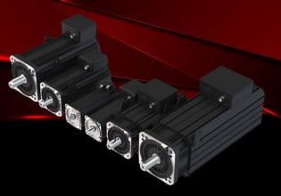
RS stepping motor part no 440-458
RS stepping motor controller part no 240-7920
ABB CT-MXS timer relay, for pulse generation.
I have assembled the components and powered them up, the stepper motor generally rotates one or two steps in one direction then either misses a step or move in the opposite direction for a couple of steps. This has been the case with various motor/controller wiring combinations. As I first thought it was just the position of 4 of the 8 wires.
First of all I am unsure if using a timer relay to provide my pulses to my motor controller is going to work. It can provide short pulses to the motor controller at 5v dc. Is this the right kind of equipment to provide a pulse to the motor controller? This is a very simple low cost project so I didn’t want to use a PLC for pulse generation.
If the components should work together I assume it must be the position of the wires that are incorrect. I have data sheets for both the controller and the motor but I have been unable to understand the wiring options on the sheets and tie the two instructions together. Nether data sheet are particularly clear.
The stepper controller has terminals PHA, PHC, PHB and PHD in that order. The hybrid motor has A, A’, B and B’.
If any one can give me a push in the right direction it would be much appreciated.
Thanks in advance.
Al


