Can IS200TREGHIBDB be replaced with IS200TREGHIBDC?

I am so happy to be in this forum.
Dear CSA, Neo, Mark vi guy and other great Engineers, I really appreciate all your explanations on this platform.
I have really learnt a lot and has really helped me in the pursuit of my carried in Instrumentation and Control.
To my question.
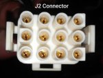
On our Frame 6B Gas Turbine Speedtronics Mk VI Panel, the type of Emergency trip card is IS200TREGHIBDB. We tried replacing this with IS200TEGHIBDC and there was loss of both AC and DC suppllies to Mk VI panel and the MCC room.
When we compared the two cards we noticed the J2 slot numbering in H1BDB is reversed in HIBDC.
Can you explain the reverse in polarity better and I want to know if we can use the HIBDC in place of HIBDB.
THANK YOU.
 
Dayo,

Can you post a picture of the J2 connector on the TREG cards (H1BDB and H2BDC)? Was either the TREG or the TRPG damaged in this replacement? Is it possible the TRPG was actually damaged and the TREG was mistakenly replaced? Were the two 24-screw terminal boards removed from the existing TREG with the wires attached and then installed on the new TREG card--or were the wires disconnected from the existing TREG and re-terminated to the new TREG (and one or two might have been improperly terminated?)?

In general--and I've never actually found this to be wrong at any time in almost 20 years of working on Mark VI (and Mark VIe)--the very last alpha character doesn't matter when replacing a printed circuit card; it simply refers to production versions of the card. What matters most is the first five characters in the string "Hnxxxx" (where "n" is a whole number (1, 2, 3, 4 or 5 for TREG cards) and "xxxx" are four alphabetic characters.

You wouldn't want to replace a H1BDB with a H1BCA, for example, but replacing a H1BDB with a H1BDC should be fine.

HnBCapture.PNG

The above quote comes from GEH-6421J, Vol. II, in the VPRO section (because the VPRO "controls" most of the functions on the TREG card. (I am presuming you are actually referring to a Mark VI, and not a Mark VIe.... MANY people make the mistake of not using the "e" when talking or writing about a Mark VIe, which while it uses many of the same I/O terminal boards as a Mark VI, is very different from a Mark VI!).

J2 appears to be the connector used to connect the TRPG and the TREG (which are used to control the fuel stop valve solenoid(s)).

J2Capture.PNG

In the snippet above, I highlighted the J2 connector designations on the TREG. I can't understand what happened, but you can see just below the midpoint of the snippet, on the left side of the TREG where positive- and negative 125 VDC are "shared" between the TREG and TRPG.

This is all the information that's publicly available from GE about the J2 interconnection between the TRPG and TREG. I could envision that J2 may have been "rotated" for some reason, but the plug on the J2 cable should be "keyed" to prevent plugging it in incorrectly. The only way I could understand a failure like you discussed is if someone forced the J2 cable connector into the J2 receptacle on the TREG in the wrong orientation.

Pictures would be excellent--and this new control.com forum is great for that, so let's use it!

This is all the information I can provide using publicly available documentation--which should be available at the site (on the HMI).

Hope this helps!
 
Thank you so much CSA for your quick response.I will try to get the J2 pictures.
TRPG was fine.The wires were disconnected from the existing TREG (H1BDB) and connected to the new TREG (H1BDC) and we experienced loss of power. The new HIBDC was removed and we got a new TREGHIBDB from our store, it was installed and everything was okay.
As you mentioned we observed that J2 numbering in H1BDB is rotated in H1BDC, so we think that the polarity is reversed ( may be can cause wrong orientation when plugging the same J2 cable connector that is initially meant for TREGH1BDB receptacle into J2 receptacle of TREGH1BDC.
J2 H1BDB board numbering
1 4 7 10
2 5 8 11
3 6 9 12
J2 HIBDC
12 9 6 3
11 8 5 2
10 7 4 1
This actually happened some months back and the Gas turbine has been in operation.

Actually, I really need your candid advise.
My company requested for some TREGHIBDB cards and the Vendor supplied TREGH1BDC but because of the experience we had we rejected the card and they claimed that TREGHIBDB is no more in production.
Is TREGHIBDB card no more in
production sir?
Also they were asking us to test the cards which we don't do with new GE MK VI card. Is it the best practise to test a newly purchase card?Thank you for your time⁷
 
Dayo,

Saying you should test the new cards you receive is a way of deflecting responsibility and muddying the waters. If you were sold a card, it should be tested and ready for installation and use.

How would you test all of the functions of the card? Did the supplier include a copy of a test procedure?

Better yet: How did the supplier test the card? What was their test procedure, and what equipment did they use, and where is the confirmation of the test results (a test data sheet supplied with the card to prove it was tested and proven functional)????

Actually, GE has stopped supporting the Mark VI (they sent owners/operators a letter to that effect a couple of years ago--and frightened MANY into "upgrading" to Mark VIe--which uses MANY of the same I/O terminal boards as the Mark VI!!!. Go figure!!!

If you look carefully at the pin-outs of the two J2 connectors, I believe (in my cursory examination) that the "new" J2 is just rotated 180 degrees from the "old" J2. Meaning, that if you rotated the J2 cable end connector 180 degrees it would have fit perfectly into the new connector, with the same conductors making contact with the same pins. The plugs are supposed to be "keyed"--meaning they can't be inserted into the receptacle improperly. You should find a couple of pins with square corners, while all the others have rounded corners; this is done to make sure the connector can only be inserted into the receptacle one way. AND, if the receptacle was rotated 180 degrees, then the pins with the square corners should be 180 degrees from their original position on the new card, meaning it would have been necessary to rotate the J2 connector to insert the cable end plug into the card receptacle, and all of the pins and conductors would have been properly aligned.

NOW, if instead of unscrewing the two screws (one at each end of the 24-terminal terminal boards) and then tugging the terminal boards off the printed circuit card--with the "field wiring" still attached to the terminal boards. and then inserting the 24-terminal boards into the receptacles on the new TREG there would have been no possibility of re-connecting the wiring incorrectly. I'm not saying that's what happened--I am saying that would be one possible explanation for what happened.

Sometimes receptacles are rotated because it is found that it makes for more robust connections and fewer problems--so that's likely what was done. But, ALL of the conductors would have been rotated 180 degrees, and the receptacle would have been rotated 180 degrees--with the keyed conductor pins--making it necessary to rotate the J2 cable connector 180 degrees to plug it into the receptacle without jamming or forcing it.

I don't know what happened--from the information provided, and without pictures--it's virtually impossible to say. It's likely the H1BDC was modified, by rotating the J2 connector/pins, to improve the robustness of the card and minimize failures (that the USUAL reason for changing cards--that and the inability to find components that were used to originally manufacture the cards).

Take the pictures and insert them or attach them to your post. That's about the only thing which is going to help at this point.
Don't fall for the supplier's obfuscation--and ask the supplier for their test data sheet, and test procedureS (plural!)--the one they use, and they one they recommend you use!!!

Anxiously waiting for the photographs...
 
These are the pictures.
As you mentioned, and from the pictures the J2 was actually rotated by 180degrees and I have been able to identify the square and the rounded corners in which by rotating the existing J2 connector (HIBDB) by 180 degrees will fit perfectly into HIBDC J2 receptacle.
We will ask for the card test data sheet.
CSA, Thank you so much for always been there.
 
Thank you for the photographs.

What is the current status of the Mark VI? Is it "up and running" or are you waiting for a new TREG?

It appears the #3 socket in the receptacle of the BDC card is somewhat melted. Can you send a photograph of the TREG end of the J2 cable, showing the pins in the connector?
 
As I mentioned earlier, the loss of power supply happened some months back when installing the H1BDC on the panel (the J2 picture I sent and that might have affected the #3 socket you noticed in the receptacle).
We actually got another spare of H1BDB from store house which we placed and the unit has been up and running since then.
I brought this question up because we do not currently have TREG in store and requested for H1BDB for future use but the vendor supplied H1BDC.
I am presently not on site but will get the picture across once I get to the site..
Thank you.
 
Good day CSA.
This is the J2 picture you requested for.
So it means that when installing the BDC, the J2 connector will be rotated by 180degrees.
Thank you so much.
 

Attachments

Top