device damage randomly during serial rs232 communication going on

Hello
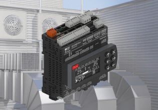
I have my device ( protocol convereter 24VDC) mounted on Din-rail in panel . this device is communicating on RS232 cable ascii communication with a VFD/Torque meter .
Now suddenly my device got damged i.e powered OFF. So what should be the issue ? I already damaged 3 devices ,
Is this grounding issue ?is any surge voltage is coming which is affecting my device. How I can check identify this ?
what care I should take while grounding connections here?
Right now complete panel has common grounded -ve supply.
 
Could well be a grounding issue - not necessarily surge.
Serial cables are generally earthed both end by the screen. Also connected to the casing which may connect to equipment metalwork. Disconnect one end with multimeter see if there AC or DC voltage measurable between cable earth and metalwork. The disadvantage with is that stray potentials may be intermittent.

In any case if may be prudent to use a signal isolator.
 
1). Did you use twisted, shielded wire/cable for the interconnecting signal transmission—AND did you ground the shield drain wire only at ONE END?

2) Did you follow the power wiring recommendations of the protocol converter for the power wiring?

3) Did you run any of the interconnecting signal wiring or protocol converter power wiring in the same conduit or cable tray as the high voltage/current wiring between the inverter and the motor? (That’s a big no-no—and a common mistake trying to save money and time on wiring….

4) Who is the protocol converter manufacturer and what is the model number?

5) What does the protocol converter manufacturer say about common mode noise rejection and/or handling?

Using the wrong kind of wire/cable, incorrectly grounding the shield drain wire(s) when using twisted, shielded wiring/cable, and running low level signal wiring in the same conduit or cable tray as the high voltage/current leads (including the mains power to the inverter!) are the most common mistakes when working with low voltage signals in an industrial environment.

Please write back and let us know what you find!
 
1). Did you use twisted, shielded wire/cable for the interconnecting signal transmission—AND did you ground the shield drain wire only at ONE END? ---the serial RS232 communication cable is NOT twisted pair . It is normal cable with schielded. shield of the cable is soldered to DB9 connector metal body on both end.

2) Did you follow the power wiring recommendations of the protocol converter for the power wiring? --- Yes,

3) Did you run any of the interconnecting signal wiring or protocol converter power wiring in the same conduit or cable tray as the high voltage/current wiring between the inverter and the motor? (That’s a big no-no—and a common mistake trying to save money and time on wiring….) ---the protocol converter is mounted in panel on din-rail & the VFD/torque meter is kept out of the panel, this VFD has 230V AC which is routed through the panel only where this protocol converter is mounted. I think 230V AC cable & Serial RS232 cable is routed into same cable duct. I am going to chk this again & confirm.

4) Who is the protocol converter manufacturer and what is the model number? -- Protocol converter is of my company only - i.e Hilscher make . Please let me know if any additional info needed.

5) What does the protocol converter manufacturer say about common mode noise rejection and/or handling? -- I need to chk with my HQ team for this & then will revert.

Thanks
 
1) Not using twisted, shielded pairs can greatly increase the risk of induced voltages which may damage some electronics as well as negatively impact readings.

You didn’t answer the question about grounding the shield drain wire at only ONE end. If it’s grounded at both ends that can cause circulating currents in the shield which will probably make any induced voltage problems significantly worse especially with untwisted wires under the shield.

5) Why aren’t you asking this question of your HQ team who would be much more familiar with the protocol converter and it’s application, instead of strangers on a World Wide Web forum who may not be familiar with the device?

Please revert back when you and your HQ team have resolved this problem to let us know what was found to be the problem and how it was resolved.

Best of luck!
 
Sorry to disturb again. I have again one query -- you mentioned above as below -
You didn’t answer the question about grounding the shield drain wire at only ONE end. If it’s grounded at both ends that can cause circulating currents in the shield which will probably make any induced voltage problems significantly worse especially with untwisted wires under the shield. --- what does this mean ? do we have to connect RS232 signal ground to shield on one end of cable ?
FYI - we already suggested here external isolator to our customer . hope this will solve the issue.
 
I assumed {above post} that your connecting cable has the screen connected at both ends.

Now imagine this scenario:
- Disconnect the earth connection on your VFD. It is now earthed (grounded) through your cable.
- Disconnect the screen/shield/drain on your cable, your VFD metalwork is now floating above earth.....
- Now back as you were - you have a loop - or you have earthed your VFD via 2 routes, earth wire and cable screen.
If you have any resistance on the earth {such as bad connection} and hardly any resistance {good bonding} on your cable screen, any earthing currents will choose the path of least resistance - your cable screen.

Some of these currents are transient and can be very high, to 100's amps. If that route is down the cable screen, through your modem chassis to PCB earthing strip to power earth - you have burnt PCB.....and I have seen the rather messy results !

So by Disconnecting the screen/shield/drain on your cable, you remove this 'loop'
Trust this helps
 
worse especially with untwisted wires under the shield

Some installers run 500m of cable then find there is 20-30vAC at one end and nothing at the other.
Then check to find the run is on traywork lying adjacent to power cables.....

If you 'throw' a magnet across 2 wires running adjacent to each other, you would get induced transient voltages in both - but the magnet went closer to one wire than the other so the induced voltage is different. if the wires are twisted together the induced voltage would be the same. This is all schoolboy physics; but you could conduct the same experiment with a transformer where induced voltages would be relatively constant.

Twisted pairs is easy which is why you have multicore cables, armoured with twisted pairs who themselves have individual screening.
 
Somebody please correct me if I'm wrong, but I'm fairly certain twisted pair is not used with RS-232. It is, however, used with RS-485, as is grounding the shield at one end.

The reason you use twisted pair with RS-485 is because RS-485 uses differential signaling. Two conductors carry the signal - one non-inverted and the other inverted. The receiver takes the difference of the two conductors' signals. By using a twisted pair, any noise/interference is induced equally on both conductors, and so will cancel out when the receiver measures the difference between the two signals.

RS-232, on the other hand, uses single-ended signaling. Each device has only a single TX signal and a single RX signal. The TX from each device is connected to the RX of the other using a single conductor. A twisted pair cable would have no benefit when using single-ended signaling protocols such as RS-232.

Typical RS-232 communication cables have a DB-9 connector on each end and the shielding is connected to the DB-9 metal housing. You will need to determine how the DB-9 housing/shielding is grounded (if at all) in each device (the protocol converter and VFD/Torque meter) before you can assess whether you have a ground loop and if it will cause issues (which can only occur if the device's local grounds that the shielding is connected to are at different voltage potentials).
 
You are correct with RS-232 but we would use twisted pair anyway !
At the time when we made all our comms cable because hard to purchase and /or just not available in a particular format, microphone cable used to be used simply for the number of surplus reels we had.
 
The RS-232 MODBUS systems I worked on a few decades ago were all spec’ed to use TSP (Twisted, Shielded Pair) wiring. Those systems quite often used what were called short- or long-haul modems and TSP between them, as well as to/from the controllers and the modems. I was ordered to more than one site that used single conductors and complained non-stop about MODBUS issues—until we ran TSP cables on the ground as a test, and the problems miraculously disappeared. (Of course, the wiring was still deemed to be in the scope of the Mark* (which it CLEARLY WASN’T because the diagram said CUSTOMER SUPPLIED—but the construction contractor was long gone and so because GE had deep pockets they were always on the hook for cleaning up someone else’s mess). Truth be told, it was the GE commissioning person's responsibility to make sure the wiring was to spec, but, when there's no accountability lots of things fall through the cracks....)
 
Twisted pair for RS-232?

I have been a fan of twisted pair since 1978 when my boss showed me how to get rid of the noise on a 0-1Vdc signal running on individual wires. The shop had no STP cable, so he put one end of two individual conductors, about 65' (30m) long, in a vise to hold the one end and then used an electric drill on the other end to twist them. When the twisted cable replaced the individual wires, the noise on the signal disappeared. That demo sold me on the idea. So I'll alway use twisted pair, even for RS-232, especially in an age of year-round, no holiday VFD noise makers. Even 4-20mA appreciates twisted pair (and shielding)

Other the other hand, I once showed up to commission a Modbus radio to the PLC Modbus port connected by about 70 feet of 14-2 Romex (parallel solid conductors, plastic insulated for residential power wiring in the US) and thought no-way will this work. Powered it up, did some configuration and it worked and 15 years later I hear it's still running (radio was replaced at 10 years). So the distance limitation of 50 feet is not a drop dead spec, it's application specific and the cabling was not by no means twisted pair, but it worked.

I believe that in RS-232 the impedance mismatch between Tx and Gnd and Rx and Gnd does not provide the same level of noise rejection as a balanced 485 circuit, but since 232 is a short run and since I get to call out the specs, I'll tell 'em use STP. I've used CAT 5 and it works OK for RS-232.
 
thanks all of you for this information.

The customer has done one thing . Now our protocol converetr is mounted slightly above to the panel . i.e the din -rail is lifted up with help of some plastic bush. I have attached photo for your reference. you will see yellow marked bush . which separtes our protocol converetr body ground connection from panel.

Today we had strange behaviour. customer just removed Serial RS232 cable from VFD while everything was running ok. & suddenly , our converter got powered off . It is not getting powered ON now.

Also I checked with panel - Serial RS232 cable & 230VAC power cable are crossing to each other into the customer panel . What is the recommendation to route these cables ?
 

Attachments

I assumed {above post} that your connecting cable has the screen connected at both ends.

Now imagine this scenario:
- Disconnect the earth connection on your VFD. It is now earthed (grounded) through your cable.
- Disconnect the screen/shield/drain on your cable, your VFD metalwork is now floating above earth.....
- Now back as you were - you have a loop - or you have earthed your VFD via 2 routes, earth wire and cable screen.
If you have any resistance on the earth {such as bad connection} and hardly any resistance {good bonding} on your cable screen, any earthing currents will choose the path of least resistance - your cable screen.

Some of these currents are transient and can be very high, to 100's amps. If that route is down the cable screen, through your modem chassis to PCB earthing strip to power earth - you have burnt PCB.....and I have seen the rather messy results !

So by Disconnecting the screen/shield/drain on your cable, you remove this 'loop'
Trust this helps
I was just going through all replies as my problem is not yet solved.

Yes the serial connecting cable is screen connected at both ends to metal part of connector. Do you want us to remove this schielding ?
 
Since your company makes the protocol converter and you now have several damaged devices, I suggest you have your engineering team inspect one of the damaged converters. This will tell you the nature of the failure and help you narrow down the cause.

My guess is that the power supply circuitry is damaged because you have conflicting ground references and/or power supply issues, and high voltages/currents are making it to your converter's power supply circuitry.

It would be helpful to create a diagram of all ground references connected to the protocol converter (i.e. power supply, RS-232, chassis ground, etc.), how they are internally connected in the protocol converter, and whether any internal isolation is used on the converter. Then on site, without the protocol converter connected, measure both DC and AC voltage differences between all pairs of ground connections that would be connected to the protocol converter.

Additionally, consider how you are powering the protocol converter and how this power supply is related to other equipment. Is the power supply derived from another power source that is shared with other equipment such as the VFD? Is the power supply isolated?
 
Top