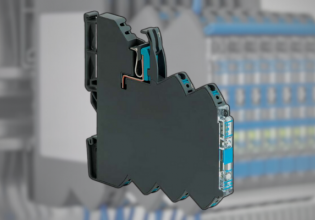
electrical mechanical control circuit; a mechanical electrical control circuit is controlling 2 signal sources through a series of input, process and output transfer of work functions. the input usually uses NO and NC push buttons where NO is for Start and NC is for Stop (Normally Open = NO and Normally Closed = NC). in the mechanical electrical system control in the process part is a combinational logic electrical circuit connection, self-holding circuit, interlocking circuit and priority circuit, using DC to AC, DC to DC, AC to DC and AC to AC relays, in a lot of processes the equipment used can relay timers and others. then in the output or workload section use indicators and 1-phase or 3-phase AC motors or DC motors, while contactor contactors can be used as a process for 3-phase motors. in the mechanical and electrical control circuits everything goes well when all spare parts, relays, push buttons are arranged safely on the control panel.


