R
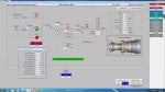
All three processors of MARK V R,S,T are reading liquid fuel flow even when GT is selected on gas fuel. checked for flow divider rotation but found not running, checked for passage through false start drain valves, but no fuel.
so please comment on what to be checked from sensors, mark v side.
so please comment on what to be checked from sensors, mark v side.