Gas Turbine Flame Detector

Y

Thread Starter

Yasnul

Dear Expert,

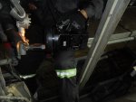
My Gas Turbine is using 4 Honeywell Flame Detector with no cooling media & no Denox injection.

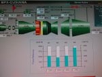
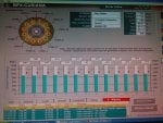
1. Is it normal to have inconsistent intensity among the 4 detectors (1 can be 180CNT, the other can be 380CNT).

2. What can be the cause of this detector reduce its intensity reading gradually, sometimes until it become 0 CNT.

3. Any better practice i.e. install cooling system, change type/model or etc.???

Thank you.
 
1. Yes. Condition of the flame detectors, age, heat, wiring, can all contribute to issues. I've also seen very fine dust particles collect in the sight tubes of the flame detectors, completely blocking the lens. Also, some flame detector mounts get bent/damaged during maintenance outages and this causes the detector to not be properly aimed at the flame. Also, the type of fuel and the condition of the fuel nozzles also affects flame detector feedback intensity. But, if you're not experiencing any higher than normal exhaust temperature spreads when this problem is occurring, it's likely a mechanical or a wiring or printed circuit card/flame detector module issue, or a problem with the detector. Have you tried exhanging flame detectors to see if the problem follows the flame detector or stays in the same combustion can?

2. It might be heat-related; we don't know how the flame detectors are mounted on your unit (inside the turbine compartment; in insulated insets of the compartment enclosure. I saw an exhaust leak once that was directing hot gases in the vicinity of a flame detector cause that flame detector to have problems. The technicians and operators wouldn't go in that area when the unit was running because they knew about the leak, and they didn't relate that the flame detector that was getting hot from the leak was the one that was intermittently and continually failing. Water cooling is usually only used on flame detectors which are located inside the turbine compartment and not in some kind of insulated "compartment". The amount of water flowing to the cooling coils of the detector can cause moisture (even ambient humidity; it doesn't have to be from foggers or evap coolers) to condense on the lens, so be careful with installing cooling coils.

3. Silicon carbide flame detectors have proven to be much more sensitive than comparable UV Geiger-Muller flame detectors. Reuter-Stokes is one manufacturer of the SiC detectors, called "Flame Trakkers."
 
R

Radhakrishnan

It is not abnormal to see discrepancies such as the one you listed. Count is an indication of the flame intensity and the state of the detector tube itself. Typically, the threshold is 64, below which it will be no-flame condition.

Differences in the combustion pattern and combustion efficiency can also be the causes of these different count values.

If your unit is EA-class or later ones, the higher firing temperature requires the flame detectors be water-cooled. This will be implemented in the original package.

The new units will have Reuter-Stokes flame scanners that are beter than the ones you have, in many respects:

* 4-20 mA output
* 24 VDC power supply
* Not damaged by polarity-reversal.
* More sensitive than the tube-types

With Mark VI Speedtronic control system, the change over is rather simple. With Mark V, additional hardware is required to convert the signal to frequency.
 
Hi everyone, I have a question.

We have 4 flame detectors in Gas Turbine MS5002C.

Sensor Honeywell, model: LG1093AA24. We have with a maintenance routine for Testing sensor with Lamp UV / IR, Dettronics Modelo: W867 ( https://www.manualsdir.com/manuals/...002-3003-uv_ir-explosion-proof-test-lamp.html ), we have Mark V.

In the test with old sensor de indication is around 150 to 200 CNT. Now with new sensor is araound 70 max 100 CNT.

Is there an explanation for this?
 
Are the flame detectors new (different) models, or just new detectors of the same model previously used?

Is there something you are doing differently when testing them?

Is the tester new or different?

is the person performing the test new at the testing?
 
Are the flame detectors new (different) models, or just new detectors of the same model previously used?

Is there something you are doing differently when testing them?

Is the tester new or different?

is the person performing the test new at the testing?
CSA,
Many years ago......

I was calibrating a MK I on Frame 7b. I had just purchased a "BRAND NEW NSTM CALIBRATED" Fluke process meter.

I had serious issues with the fuel valve calibration and adjusted the MK I accordingly. NEWBEE me had no idea that adjusting the fuel valve LVDTs required a true RMS meter.

Had to start over!!!!

Hopefully, the original poster may be able to learn from my stupidity of years ago.
 
Hi @CSA, thanks for your time,

Are the flame detectors new (different) models, or just new detectors of the same model previously used?
New detectors of the similar model previously used, but the only diference is cable length (LG1093AA44).

Is there something you are doing differently when testing them?
No, the procedure is the same, please look the image Flame testing

Is the tester new or different?
Tester is the same previously used.

is the person performing the test new at the testing?
No, the person is the same, we have a maintenace group since 5 years.
 

Attachments

The sensor manual only especific the time of change for this model are 2 years.

Are ther a relasionship betwet time use vs CNT??? We made another test with all sensor in the same channel, the result were the same. But the new sensor have 6 meters more of cable length. Are there difference for this length?
 
In my personal experience, the leads can be cut to length; there is no special connectors used on leads.

How are you “coiling” the extra lead length? Could that be the problem?

I have always just cut the extra length off the detectors before connecting them with set-screw wire nuts or crimp terminals.

Also, the test method doesn’t seem to be very precise or scientific.

Differences (large differences) in counts (flame intensity) are usually the result of fuel flow differences which can be caused by nozzle orifice plugging or excessive wear. BUT such fuel flow and intensity differences would generally be accompanied by excessive exhaust temperature spreads. If the unit is not having high exhaust temperature spreads when experiencing large differences in counts would tend to indicate other problems (other than fuel/combustion issues).
 
Maybe you received a bum (bad) flame detector. Or it got damaged in shipment or during installation. Happens. (Both)

Please write back to let us know how you fare in solving this problem. I can't tell from the pic's but if the unit had DLN combustors and there is no cooling water coil I don't think the flame detectors are going to last very long. The data sheet provided by BH mentions DLN applications; of course that doesn't always mean they are used only on DLN applications.
 
Hi @CSA, we finally installed the old sensors, but I don't know what happened to the new sensors, because in the last maintenances we had the same problem. Now the turbine is online.

In the pictures, there aren't differences in exhoust temperatures, but we deduce that the combustion is uniform, so the signal of flame detectors don't tell us the true intensity of flame.

The length of all sensors are the same, 30 cm. I was looking in the manual about the combustion flame and these values are on/off signal, they should not be used to calculate anything. So, we only focus on that in the test all the sensors are above the threshold value and hat they are within the useful life time (2 years).

Could you explain to me if I'm wrong?
Thanks very much.
 

Attachments

Rialagas,

Yes; the output of the Geiger-Muller flame detectors is a frequency, that is zero-based (which makes it on/off in nature). HOWEVER, the frequency IS a measure of flame intensity. The on/off nature has nothing to do with the frequency. With the Mark V, GE Mark* turbine control systems starting using the frequency to indicate flame intensity. For some people, this is too much information. And, it's really only necessary for units with DLN (Dry Low NOx) combustion systems with staged combustors. If the unit has conventional combustors, flame intensity is pretty much inconsequential and just plain too much information that can be confusing (like this thread) and misleading. There are only four flame detectors on your unit; and if it has conventional combustors, flame intensity in four (of 10) combustors is pretty useless. The only time it's not is when one (or more) of the combustors with a flame detector has a combustion problem that results in high exhaust temperature spreads. Then flame intensity MIGHT be useful information to determine which combustor(s) are having combustion problems--IF the problem is flame-related. Again, unless the unit has staged combustion systems, flame intensity information is pretty useless. It's just that the people who make the HMIs thought it should be included on the HMI, when it's not really useful except in particular circumstances.

It's very common for flame detector sight tubes to get bent, to be misaligned. I have also seen the hole in the combustion liner that the detector has to look through be slightly off center (even with GE-made/supplied combustion liners). Also, the cleanliness of the sight tube (pipe) can have a lot to do with intensity indication; rusty tubes are not as good as clean ones. Really shiny tubes can also provide false signals. I have also been to NUMEROUS sites where there is a gate valve used to isolate the flame detectors when performing an off-line water wash, and the gate valves were not fully open, or they had rusted and come apart with the gate partially blocking the sight tube (pipe).

So, you are wrong about an on/off pulse not being useful for anything. Did you know that the speed input to the Mark* is basically a pulse (zero-crossing, not zero-based--but it's a pulse). And the frequency of the pulse is what the Mark* uses to determine shaft speed (RPM)?

And, just because some flange-head bolted the flame sensor to the combustion can and some sparky screwed on a flame detector to the sight tube (pipe) doesn't mean the alignment is correct or the sight tube is clean or the view is unobstructed.

Hope this helps!

Blessed day!
 
I know I'm not addressing your concern about how one flame detector can be reading so differently when using the test instrument you have. Again, it's just possible that the flame detector you received is faulty, was damaged during shipping or installation--bad components. Maybe it was even inadvertently connected incorrectly (these Geiger-Muller flame detectors are VERY sensitive to polarity).

One think you could have done was to move the suspect flame detector to another input channel and see if the problem followed the flame detector to the new input channel. If it didn't then try a different flame detector on the input channel the suspect flame detector was first connected to and observe it's operation.

Something I'm also getting extremely bad about when responding to posts here on Control.com is to ask about Diagnostic Alarms and Process Alarms. I know that almost every person on planet Earth with a Mark* turbine control system ignores Diagnostic Alarms because they have all been told and believe that Diagnostic Alarms can't trip a turbine. [And, while it's true that a single Diagnostic Alarm can't trip the turbine there ARE combinations of Diagnostic Alarms which will trip the turbine. And, NO--there is NO list of which combinations of Diagnostic Alarms can trip a turbine--there are literally thousands of Diagnostic Alarms on some Mark* system, and it would be impossible to compile such a list for every turbine/Mark* system.] Diagnostic Alarms are intended to warn conscious operators and I&C (Instrumentation & Control) technicians of a problem with the health of one or more input and/or output channels of the Mark*, a problem with a device connected to the Mark*, a problem with communications between Mark* components, etc.--all of which can lead to a condition which could result in a turbine trip if left unattended.

Most sites also ignore Process Alarms--because as long as the turbine runs, or starts, they believe any alarm is just a nuisance alarm because the Mark* will protect the turbine and auxiliaries. And, that is simply not true. If the Mark* were designed to protect the turbine and auxiliaries from EVERY possible condition which would damage the equipment without any operator intervention most people would consider the Mark* to be unreliable--because it would shut the unit down frequently at most sites because of lack of attention on the part of operators and poor maintenance practices. There are some conditions--and some circumstances--where the turbine and its output (torque; electricity; exhaust heat; etc.) are critical and the unit can be operated, possibly at a reduced load, without risk of too much damage, so the designers made sure there were Process Alarms to warn of impending problem (though the Alarm Text Message isn't always very explicit) and let the unit continue to run--allowing operators and their supervisors to make decisions about how to proceed, if at all. So, while the Mark* protects against most problems--which if left unattended to for even a split second would severely damage a turbine (such as low-low oil pressure, or high-high vibration, etc.), other conditions (such as high atomizing air temperature, or high wheelspace temperature, etc.) are left to trained, knowledgeable, experienced people to attend to and deal with.

I know all of this alarm stuff isn't seemingly pertinent to your issue--but it might have been if I'd asked about alarms present during your testing--and maybe not. But, the point is: When experiencing problems like this, checking the Diagnostic Alarm display can possibly help identify an issue which is the cause of the problem being experienced or contributing to the problem being experienced. And, as was written, the overwhelming majority of people ignore Diagnostic Alarms because they don't think (and have been told) they are not important or the alarm text messages are cryptic and there is no "help" for troubleshooting the alarm(s). And, I often find when I travel long distances to a site to assist with a problem that there have been existing Diagnostic Alarms for weeks or months which, if attended to, would have helped to quickly resolve the problem before it caused an outage.

I hope you find a satisfactory explanation for your issue. And, I hope you will write back to share it with others on this forum. These posts are all available for anyone to read at any time--next week, next month, next year, next decade. And, feedback from the original poster on the resolution provides EXCELLENT information for those having the same or a similar problem about what worked to resolve the problem and even what didn't. "Feedback is the most important contribution!"(c) here at Control.com--it really is. It's what sets the information provided on this forum apart (in a good way) from other, similar forums.
 
Top