ModScan64 error message: "MODBUS message TIME-OUT"

I'm trying to retrieve data from an AC/DC transformer (http://www.growatt.co.nl/show-42-588.html datasheet and other technical documentation can be found in English if you scroll all the way down) using Modbus. I stuck an RS485 cable into the device with one end and into my PC through a USB connector with the other.

I then opened ModScan64 and set it up according to this video
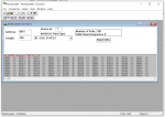
(COM port 3, baud rate 9600, word length 8, parity none, stop bits 1). But I'm not getting any data despite the poll count going up. I'm also getting an error message that reads "MODBUS message TIME-OUT" (see attachment).

Does anyone have an idea what I'm doing wrong? I also have a siemens LOGO PLC which allegedly is Modbus-compatible. Could the solution be in that?
 

Attachments

There's about 50 things that can be wrong.

I can't find the Max 50 on the English version of the web site (one has to know all the product categories, which I don't, and I can't find a search function.)

So, here's some RS-485 issues that are commonly encountered:

1. Without seeing the inverter specs, are you sure it talks Modbus RTU over RS-485? RS-485 is a hardware bus and there are lots of protocols that run over RS-485 that are not Modbus RTU, like Profibus DP.

2. "I stuck an RS485 cable"

There are commercial communications cables with twisted pair and a 120 Ohm characteristic impedance suitable for RS-485, but there are no generic Modbus RS-485 cables because the connectors are not standardized. The cable part of "an RS-485 cable" is likely to be OK, but the connectors?

If the connections are not screw terminal connections, like RJ-45 or DB9, check and re-check and re-check the wiring. A to A, B to B, or (+) to (+), (-) to (-), or A to (-), B to (+). Many RS-485 screw terminal connections provide terminals for full duplex 4-wire RS-485, and jumpers need to be installed for 2-wire use. [jumpers connect (Rx+ to Tx+, Rx(-) to Tx(-)]

3. There is no agreement in the industry as to which driver line is which. Although A should connect to A and B to B [or (+) to (+), (-) to (-)], sometimes opposite labeling by different vendors means that the driver lines have opposite functions. Connecting driver lines backwards does not damage them, but communications is impossible. If all other comm settings are correct and there's no communications, try swapping the A and B lines on one end to see if this line labeling situation is the case.

4. For short distances and at baud rate less than 9600 baud, the terminating resistors at each end of the bus are not needed. Longer distances and higher baud rates need termination resistors on each end. Terminating resistor connects across the A and B or (+) and (-) terminals.

5. The serial settings for both ends must identical: baud rate, parity, stop bits, word length by definition is 8 bits. Any mismatch of serial settings will produce "Device not Connected" error. Specifically, the Modscan settings must match those of the inverter. How to do you know what the inverter serial settings are? Assuming that the video you reference is a generic video about Modscan and not a tutorial on connecting to the specific inverter in question, there is no reason to believe that the connection settings used in the video are valid. You must know (and confirm) the serial settings on the inverter.

6. You mention 3 Modbus devices: the inverter device, Modscan, and a Logo PLC.
Modbus RTU by definition can support only one master on the bus. Modscan is a master. The inverter is almost certainly a slave. If the Logo PLC is an active master, there will be communication packet collisions resulting no communications. If the Logo is not operating as a master, it can passively reside on the RS-485 bus, but it cannot be active in combination with Modscan.

7. The COM Port 3 used in the video has to match the virtual COM port used by your USB/RS-485 converter. You need to check the virtual COM port under Windows' Control Panel > Device Manager > Ports, which will provide the actual COM port used by the converter.

8. 2-wire RS-485 is actually 3-wire, there should be a signal ground. If there is a signal ground on both ends, connect them. If there are no signal grounds and the installation is not bench-top testing, but in the field, then there is a probability that there is a ground loop between the devices that is disrupting the communications. The use of an RS-485 repeater/isolator will usually resolve a ground loop problem.

Comments on using Modscan

When running Modscan, particularly with RS-485, it pays to limit the number of registers being polled or requested. The "length" setting determines that number of registers. Although a high number will not cause the error you see, a high number makes it awkward to analyze what's happening because of the volume of data. Try starting with a length of 2.

There's no mention of what data you're looking for. You need to get the inverter's Modbus map and use then use Modscan's 'Address' field to get the correct register address for the data you're looking for. Just because the video used coil status starting at 00001 does not mean that there's any useful data in the inverter at those registers.
 
Top