MULTI VOLTS INPUT

  • Thread starter Pierre Desrochers
  • Start date
P

Thread Starter

Pierre Desrochers

Hi all -

Again I ask the list to help me solve this request :

We see more and more modules... having specs which list the supply as being able to accept 24 Vac to 240 Vac AND 12 Vdc to 240 Vdc ...

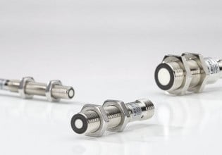
We can connect ANY of those voltages to the supply wires for these devices (proxi, photcell, etc)

What circuit is involved in this... is it a standard chip bought from supplyers like DigyKey or is it a custom circuit.. if so can you
provide a diagram for me to understand ?

Thanks again guys -

Pierre
[email protected]
 
There are some assumptions made with these products. I believe in your context these devices use smart power supplies. They measure the incoming voltage and make a decision based on this measurement then take action: turn on appropriate switch for the right power supply configuration. You could probably manage this using all analog (ugly and expensive) but the easiest is to use a microcontroller.

Steve, BSEE
 
J

Johan Bengtsson

Ok, I don't know exactly how they did it, but I know how I would have done it, it is not actually that complicated to do:

1. I do of course decide what voltage I want to use internally in the device I am making, example 24Vdc (For this to work it is easiest if it is some DC)

2. I then (if necesary) decide to use a primary DC
voltage, probably somewhat higher that I allow to vary somewhat, and use that one to make the stabilized voltage I want, the easiest solution would be to use say 28-33 something Vdc (ie it is allowed to drop down to 28V and it wouldn't hurt anything if it goes to 33V

3. The input voltage is feed thru a low pass filter (inductor + capacitor) removing frequencies above about some 100Hz to 10kHz (depending on the switch frequency, see below). The filter should well enough let the possible input AC frequencies pass of course

4. The input voltage is rectifyed as the first step This handles the input voltage regardless of if it is AC or DC

5. The recified input voltage is then switched and feed thru an inductor, or a transformer if insulation is needed

6. The output from (5) is fed to a large capacitor (large enough to hold the voltage (2) high enough when the (possible) AC input is near 0.

7. The average voltage at (6) is regulated to be approx 30V or so. the control signal is affecting the PWM of (5)

Design issues:
A high switching frequency will make it easier as the filter will be cheaper and so will the
inductor/transformer used in the voltage conversion process
The components have to handle the power needed at both lowest possible input voltage (= high current) and the highest possible input voltage (= high voltage). You can extend the limits as far as you want, it is only a question about money spent.

This design have the additional benefit of taking a sinus formed current from the source if it is AC input.

Johan Bengtsson
----------------------------------------
P&L, Innovation in training
Box 252, S-281 23 H{ssleholm SWEDEN
Tel: +46 451 49 460, Fax: +46 451 89 833
E-mail: [email protected]
Internet: http://www.pol.se/
----------------------------------------
 
Top