Reading and writing Dual-tone-multi-frequency, DTMF to PLC Variable Registers

  • Thread starter Anibal Hernandez
  • Start date
A

Thread Starter

Anibal Hernandez

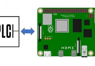
Does anyone know how to read and write Dual-tone-multi-frequency, DTMF to PLC Variable Registers? Same way we access bank account information via phone using Touch Tones on the phone keypad dial

I need to convert these Touch Tones to actual real numbers and store them in Variable Registers, at the same time I need to get these numbers out of the PLC and convert these to Touch Tones.

I have access to DTMF generator (Encoder-Decoder) I just don’t know what to do to get them into the PLC.

For example let say that someone calls and push 1234 on the phone dial, at the other end of the line I need a way for the PLC to listen to these Tones and store 1234 in a Variable Register.

Does anyone know how to do this?
 
T
thoughts on DTMF input to PLCs - Generic.

1. have a look at the NTE site and call up NTE1690 - which is a DTMF generator. Generally you will have more trouble purchasing an old style keypad DTMF generator than the receiver.
DTMF receivers have a valid tone output so that gives a clue as to how to implement the receival.

www.nte.com

Holtek are one of the few companies making the keypad DTMF encoder chips without lots of whistles and brass knobs on them [see mitel].

You wire the 4 binary outputs into inputs of your target PLC. Most DTMF receivers sink to ground on the output pins. Therefore you will almost certainly have to use optocouplers eg 4N28 with an appropriate loading resistor on the diode side or possibly telecom style reed interposing relays provided the DTMF output can sink the required 5-8 mA.


I assume that you want to use a terminator symbol to end the data entry - as per carriage return on a conventional keyboard.

Each time a digit is passed through you run the following algorithm:

digit count = 0
for ; ;
If valid tone signal
read the four inputs as a binary number
if <> # symbol equivalent number // do not have the cross reference table to hand.
place binary number into current register
increment current register pointer
increment digit count
else
move final number to process code address
// do this by decrementing two pointers and passing the digits
// or by converting to a single binary number by multiplying
// the stored number by incrementing powers of ten,
// depending on how the PLC represents numbers internally.

reset memory pointer
digitcount = 0
end if
end if

However you need to look at the bigger picture - how much is it going cost to implement all of this ?

$80 per hour x 3 days of technician's time is $1920 [plus parts and the fact that a replacement unit will have to be kept on hand if this is a serious process plant]. Compare that with a pre built user interface - have a look at the interface panels section of www.automation.com.au for example - or perhaps the manufacturer of the PLC you want to use has a custom panel.

Look at the HMI too - how is the user going to know he did not double press a key - is there going to be a numeric feedback ? Are there multiple entries for different process points to be made - are you going to handle this by another keypad or a BCD wheel set that selects the register that is going to be modified ?
The user needs some sort of warning that an invalid number has been entered - eg a very low or high set point -- the list goes on.

The whole matter needs a detailed user specification that has to be refined before any hardware work is done.

Regards,

TE.Fidler, Adelaide, South Australia
[email protected]
 
T

Tomy Zacharia

Dear all,
The DTMF encoder takes a logic high on two pins, which corresponds to the intersection of a matrix representing the keys on the touch pad of a telephone. Thus for generating DTMF tones from PLC, you would need 8 digital outputs set up as two sets of four each. The combination of two lines sets up one of 16 possible combinations. The DO of the PLCs will have to be
either voltage scaled or if possible TTL outputs will need to be used.

A DTMF decoder works the other way round. It makes a combination of two lines high based upon the input tones. Again 2 sets of four lines would be required. Signal interface will need to be done for TTL level signals or whatever a particular decoder puts out. The PLC will need to implement a decoder/encoder logic of its own to make sense of the signals. What to do with the data is left to imagination.

Thanks

Tomy Zacharia
 
Top