Short, Incomplete, and Unknown Exception Responses

Interface Details:

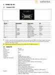
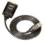
Modbus RTU via RS232, Serial to USB Converter
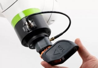
Sartorius Biostat RM (PLC Controlled Device, Vendor non-standard Pinout) to Windows 10 Laptop
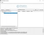
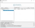
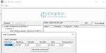
Utilizing Chipkin CASModbusScanner Software to Test

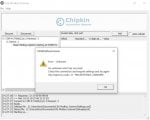
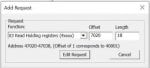
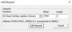
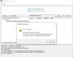
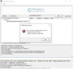
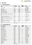
Issue - While the Device does respond to a Poll, I have only once gotten what seemed to be a complete response (trying to read/poll all holding registers), which appear to be offset of 7000, length of 53. Most of the time I get exception codes (-2) Message too Short, (-4) Invalid Function Code and (-8) Response Unknown.

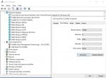
Currently only using (3) wires - TX, RX, and Ground (note Device has both a "Signal Ground" as well as a "Field Ground"; but utilizing Signal Ground does not produce any response from device (poll timeout). Adding additional wires to CTS/RTS and/or DTR/DSR have not provided any additional benefit (have tried most all combinations of crossed and straight through, as well as several combinations of loopbacks to defeat handshaking - no luck).

Chipkin CasModbusScanner Software is a free download (not promoting it, but it is what I am using to test).

Looking for any suggestions/advice on things to try or if I am missing something obvious...it should not be this difficult.
 

Attachments

I don't know what the leading character D represents. So, I'm assuming that the registers appear to be Holding Registers numbered as zero-based decimal values.

I always start by reading one register with a known value to compare against to check and make sure all the serial settings and my guess at register addressing is correct. That fact that you get a valid error message says that the serial connection is working.

There's no guarantee that the spare registers are valid registers, even though the spare bits at D7052 and D7052 are likely zeroed out. D7051 might be an invalid register, which calls up an error if a read is attempted.

I'd try to read (4)7001 [D7000] through(4)7014 [D7013] in one read without getting into the spare register memory locations.

Same for the (4)7021 [D7020] through (4)7039 [D7038].
 
Thank you for your response David - per your advice, I ran (3) tests, based on only polling registers

1) 47000-47013 (mix of Words & UINT) - returned Error (-8)
2) 47020-47038 (all UINT) - returned Error (-8)
3) 47050 only (BOOL) - returned "Error, Modbus message invalid length, short"

See test setup and result screenshots attached.
 

Attachments

Repeated the (3) tests, adjusting polling registers by (+1) for each -

1) 47001-47014 (mix of Words & UINT) - returned Error (-8)
2) 47021-47039 (all UINT) - returned Modbus Error Code 0x8E and Modbus Exception Code 0x80
3) 47051 only (BOOL) - returned "Error, Modbus message invalid length, short"

See test setup and result screenshots attached.
 

Attachments

I initially misread the map as zero based and it is not. The statement at the bottom of the page in the SARTORIUS 1 attachment in post 1 says that the registers are one-based, starting at 40001. The master queries in post #4 are one-based addresses.

The reply messages make no sense as Modbus RTU replies, nor as Modbus ASCII replies because the slave is slave 0x01 which should be the first byte in both the query and the response. The first byte in the reponse is consistently 0x33, which makes no sense.

It appears that the Sartorius has fixed serial comm settings of 57600k baud, 8-E-1. The screen shots say that the master is 57600 baud, E-8-1, which matches, so it's not due to serial settings mismatch.

The Sartorius 1.jpg attachment says that FC03 reads from either DM memory or EM I/O memory. The map calls the Holding Registers D7xxxx. Maybe the replies are coming from the EM memory, not the DM memory, although that doesn't explain the bad values for the slave ID (0x33) . Is there some other setting for making DM memory the primary Modbus memory?

Is there a setting somewhere else in the Sartorius that enables/disables Modbus as opposed to some proprietary protocol used on the same RS-232 port, where the replies are replies in a proprietary protocol?
 
I initially misread the map as zero based and it is not. The statement at the bottom of the page in the SARTORIUS 1 attachment in post 1 says that the registers are one-based, starting at 40001. The master queries in post #4 are one-based addresses.

The reply messages make no sense as Modbus RTU replies, nor as Modbus ASCII replies because the slave is slave 0x01 which should be the first byte in both the query and the response. The first byte in the reponse is consistently 0x33, which makes no sense.

It appears that the Sartorius has fixed serial comm settings of 57600k baud, 8-E-1. The screen shots say that the master is 57600 baud, E-8-1, which matches, so it's not as serial settings mismatch.

The Sartorius 1.jpg attachment says that FC03 reads from either DM memory or EM I/O memory. The map calls the Holding Registers D7xxxx. Maybe the replies are coming from the EM memory, not the DM memory, although that doesn't explain the bad values for the slave ID (0x33) . Is there some other setting for making DM memory the primary Modbus memory?

Is there a setting somewhere else in the Sartorius that enables/disables Modbus as opposed to some proprietary protocol used on the same RS-232 port, where the replies are replies in a proprietary protocol?
David,

Thank you again for the detailed and thoughtful response - very appreciated.

Late last week I was sent the full electrical schematics for the unit which I am trying to communicate with, which is controlled (overall) by an OMRON CJ1M-CPU23 controller. While this controller does have a 9-Pin Serial Port on it, it is not inherently capable of MODBUS RTU or MODBUS ASCII, per the following Blog Post I found online (See posting by "PMCR Expert" on 8 Jan 2011 that starts with "The full implementation of 'Serial Gateway' involves 3 specific FINS Commands):

https://forums.mrplc.com/index.php?...-of-serial-gateway-modbus-on-cpu-serial-port/

So it appears the comms we are getting back are of the "CompoWay/F" variety, whatever that is.

For the unit I am dealing with, there is the option to install a Communications card (OMRON CJ1W-SCU21-V1) with (2) ports that can be set to convert comms to MODBUS RTU or ASCII, and I am in the process of running this option down currently.

Thank you again for the detailed look into this issue - it was super frustrating as it started out with a non-standard vendor-implemented 9-pin pinout (including a 5V Source pin), and then once I got some kind of response, that response was/is also garbage.

Nick H.
 
Yes, the dreaded proprietary protocol, CompoWay/F, as you say, whatever that is.

Good find on that thread on the complexity of Omron's Modbus RTU and port useage. Presumably the optional "Modbus" card will work as expected with the Modbus card.

Out of curiosity, how did you wire the DB9 port to get RS-232 working at all? Tx, Rx, and signal ground only? Or did you mess with the handshaking lines?
 
Yes, I did end up with just TX, RX, and Ground, and had no luck adding any other connections or loopbacks to defeat handshaking...spent more time on that than I'd like to admit (I tried almost every iteration possible I think).
 
Top