Synchronize

A

Thread Starter

assim basil

I am operation engineer, and we have gas turbine Frame 6, MKV TMR Speedtronic control type.

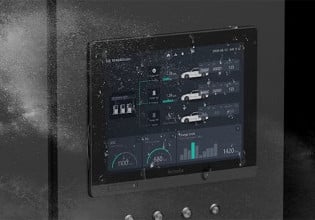
When we start the turbine and reach the full speed no load we tried many times to synchronize the unit. But we failed because the the values of the voltage and frequency for generator and grid in the operator screen interface <I> were unstable, and its values fluctuted between 0 to 50 hz and 0 to 11 kv. But the same values in the gauge meter in the generator protection panel were stable. So please, can anybody help us to solve this problem?
 
Hi there,

There seems like another case in this site and my answer will be the same. Screen data has nothing to do with synchronization. Synchronization happens too fast for the screen to catch, especially <I> units. To know what is going on with your unit, ask your MKV guy to run a trend with the voltages and MKV synch permissive POINTS. The scan rate has to be quick, like 32 scans per second - YES, MKV can do that - and then you will find what is the issue.
 
B

Bob Johnston

Sounds like a very similiar problem to the one posted by Mambo above on the same date. Do what he did first and check the incoming voltages on the PTBA terminal board at the <P> controller (check Appendix D in Application Manual, page D-53)If you don't have it, Bus Volts on 29,30 & 31 Gen Volts on 32,33 & 34 Three Phase current on 73,74 75,76 77,78. If all is OK there, then follow the same instructions in the reply to Mambo's post.

Good Luck.
 
Have you used the Prevote Data Display to look at the voltage input signals to try to get a sense for where the problem might be?

Have you looked at the Signal Flow Diagrams in Appendix D of the Mark V Application Manual, GEH-6195?

Have you recently replaced the TCEB or the TCTG or the PTBA?

Follow the Bus- and Gen PT signals through the PTBA to the TCEB on the next page, then back to the PTBA on cable JU then to the TCTG on JN then to the TCQA on JDx (JDR for <R>, JDS for <S>, JDT for <T>) then to the TCQC on JE and then to the DCC on 1PL. Complicated, but that's the path. You need to check all the ribbon cable connectors in the path(s) to be sure everything is properly seated.

It's been reported before on control.com that corrosion of the ribbon cable connectors has caused problems. GE recommends using a conductive grease (lightly applied by rubbing a thin layer on the ribbon cable connector before plugging it into the card connector; don't use too much, but make sure there's enough to coat the pins and get carried into the connector sockets). Depending on how recently you purchased spare printed circuit cards, you may find some tubes of conductive grease in the boxes with the cards. A little goes a long way.

Synchronizing occurs in <R>, <S>, and <T>, and on the TCEA cards in <P> (<X>, <Y>, and <Z>). The "wide" synchronization window occurs in <R>, <S>, and <T>. The narrow synchronization window occurs in <P> on the TCEA cards. I'm guessing that something's amiss in the cabling that takes the signals from <P> core to <R>, <S> and <T>. And that the wide synchronization window is not getting the signal it needs--but that's just a guess.

Let us know what you find.
 
Top