Why IGV Capped at 57 degree

GE gas turbine frame 9e
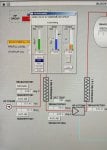
Please find below an image of IGV HMI
In which the IGV reference temperature is 53 degree .. and because we are working in combined cycle the IGV angle cannot be below 57 degree .. this situation leeds to a decrease in gas turbine exhaust temperature and in some situation when exhaust temperature decreases too much it becomes lower than the steam temperature entering the STG and when this happens the unit trips
my question is why the IGV is capped at 57 degree and cannot go below this degree ? I asked this question to our control engineers and i didn't get a good answer .. all they said that its a global set point for all frame 9e units when working in combined cycle and it cannot be changed .. is there any solution for this problem ? Thank you IMG_20210511_073510.jpg
 

Attachments

Makarem,

The minimum operating IGV angle for many GE-design heavy gas turbines is 57 DGA and that is to protect the axial compressor from damage. Unless the unit has DLN-I combustors AND IBH (Inlet Bleed Heat) and IBH is active while the unit is at Part Load (less than Base Load) then the minimum allowable IGV operating angle when at rated speed will usually be 57 DGA—again, to protect the axial compressor from damage caused by stall/surge due to lower than design air flow into and through the axial compressor. The minimum IGV operating angle is a function of the design of the axial compressor.

The solution? Run the unit at higher loads to achieve higher exhaust temperature. It looks like the unit is already operating with IGV Exhaust Temperature Control active (which keeps the IGVs closed as much as possible to maximize exhaust temperature), but without being able to see the program running in the Mark* and without knowing a lot more about the configuration of the unit that’s all we can say based on the information provided: The minimum operating angle for a typical GE-design Frame 9E heavy duty gas turbine running at rated speed without IBH active is 57 DGA and that is determined by the design of the axial compressor to protect the axial compressor from damage caused by stall/surge due to low air flow into and through the axial compressor.

You could ask GE or a person/company with axial compressor design experience if there’s something which could be done that is not injurious to the machine to solve your problem, but it really sounds like whoever designed the HRSG and the steam system didn’t provide good information to the steam turbine manufacturer, or purchased the wrong steam turbine for the application, or the plant operation has changed since it was designed. But, without much more information this is all that can be said. Your controls people are correct—based on the information provided. And the solution is to not operate at loads that cause the exhaust temperature to be less than the trip setpoint of the steam steam turbine.

Blessed day.
 
Thank you for your detailed answer
I have another question related to this one
Our STG inlet HP super heat steam temperature setpoint is 998 F and this temperature maintained by the attemperation system after the first stage superheater going to the 2nd stage super heat which then enters the STG and that constant temperature (998 F)
My question is
Is that setpoint can be changed or is it a constant setpoint for this STG and cannot be modified
If it can be changed .. what is the way to change it .. is it through the attemperation valve by changing the setpoint of the temperature refrence at the valve controller or is there another way ?
 

Attachments

Makarem,

Thanks for the kind words.

People who know me are having a big laugh right now.

I have little patience most of the time. Perhaps because I am near retirement I seem to have a little more. But a read of my reply to another current thread will prove I really haven’t (become any more patient).
 
Thank you for your detailed answer
I have another question related to this one
Our STG inlet HP super heat steam temperature setpoint is 998 F and this temperature maintained by the attemperation system after the first stage superheater going to the 2nd stage super heat which then enters the STG and that constant temperature (998 F)
My question is
Is that setpoint can be changed or is it a constant setpoint for this STG and cannot be modified
If it can be changed .. what is the way to change it .. is it through the attemperation valve by changing the setpoint of the temperature refrence at the valve controller or is there another way ?
Hi All

I would ask following question :
What is Controls system used ..Is that schreenshot showing DCS view or STG governor/controller view...

What is Median Meaning ..

How many attemperator are installed ...operating ...can you change /modify reference setpoint one of the other one is existing...

Is that output value showed in Faceplate for Spraywater control valve...

You have the faceplate open so we can see taht there is process var/setpoint /output value...so it seems that it can be modified..

But question is whaT are you attenting to do by such manipulation...can you tell us ...

DCS should handle kind of operation mode ...

Looking to hear back from you soon
 
Top