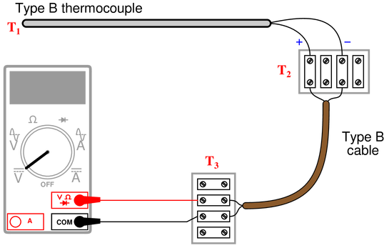
Calculate the amount of voltage “seen” by the voltmeter given the following measurement and reference junction temperatures:
{\bullet} $T_1 = 589~^{\circ}F$ ; $T_2 = 63~^{\circ}F$ ; $T_3 = 70~^{\circ}F$ ; $V_{meter} =$
{\bullet} $T_1 = 821~^{\circ}F$ ; $T_2 = 69~^{\circ}F$ ; $T_3 = 73~^{\circ}F$ ; $V_{meter} =$
{\bullet} $T_1 = 1524~^{\circ}F$ ; $T_2 = 91~^{\circ}F$ ; $T_3 = 105~^{\circ}F$ ; $V_{meter} =$
{\bullet} $T_1 = 1922~^{\circ}F$ ; $T_2 = 102~^{\circ}F$ ; $T_3 = 135~^{\circ}F$ ; $V_{meter} =$
All answers based on ITS-90 thermocouple table values:
{\bullet} $T_1 = 589~^{\circ}F$ ; $T_2 = 63~^{\circ}F$ ; $T_3 = 70~^{\circ}F$ ; $V_{meter} = 0.463~mV$
{\bullet} $T_1 = 821~^{\circ}F$ ; $T_2 = 69~^{\circ}F$ ; $T_3 = 73~^{\circ}F$ ; $V_{meter} = 0.953~mV$
{\bullet} $T_1 = 1524~^{\circ}F$ ; $T_2 = 91~^{\circ}F$ ; $T_3 = 105~^{\circ}F$ ; $V_{meter} = 3.378~mV$
{\bullet} $T_1 = 1922~^{\circ}F$ ; $T_2 = 102~^{\circ}F$ ; $T_3 = 135~^{\circ}F$ ; $V_{meter} = 5.294~mV$
Note: all temperatures at $T_2$ are irrelevant because this is a junction between similar metals (type B wires connecting to corresponding type B wires). The reference (cold) junction is where the type B wires connect to copper, at temperature $T_3$.
For all worksheet questions, temperature conversions and table lookups might be necessary.
For conversions, refer to Control Automation’s temperature conversion calculator and for table references, refer to the National Institute of Standards and Technology (NIST) website.
This thermocouple is installed improperly:
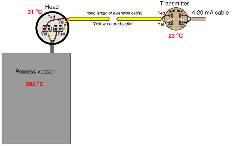
Identify the nature of the problem, and then calculate the millivoltage seen at the screw terminals of the temperature transmitter given the temperatures shown. After that, calculate the temperature interpreted by the transmitter assuming it has cold junction compensation (CJC) enabled.
The extension wire has been connected “backwards” to the thermocouple. Yellow should connect to yellow, and red to red!
Seeing how the four junctions’ voltages interact is best done by drawing the circuit with each junction explicitly labeled as to polarity. You will see that the process and reference (transmitter) junctions are aiding each other, and the two junctions formed at the head are opposing the first two (but aiding each other). The formula for calculating voltage at the transmitter screw terminals then becomes:
$$V_{terminals} = V_{592^oC} + V_{23^oC} - V_{31^oC} - V_{31^oC}$$
$$V_{terminals} = 24.57~mV + 0.92~mV - 1.24~mV - 1.24~mV$$
$$V_{terminals} = 23.01~mV$$
If the transmitter has CJC enabled, it will add 0.92 mV to compensate for the reference junction, making the interpreted (measurement junction) voltage equal to 23.93 mV. This equates to 577 °C, which is substantially cooler than the real process temperature.
Part of this solar-heating control system uses a dual-thermocouple circuit to compare the temperature inside the solar collector against the temperature inside the house, preventing the circulation fan from running if the house is ever warmer than the collector:
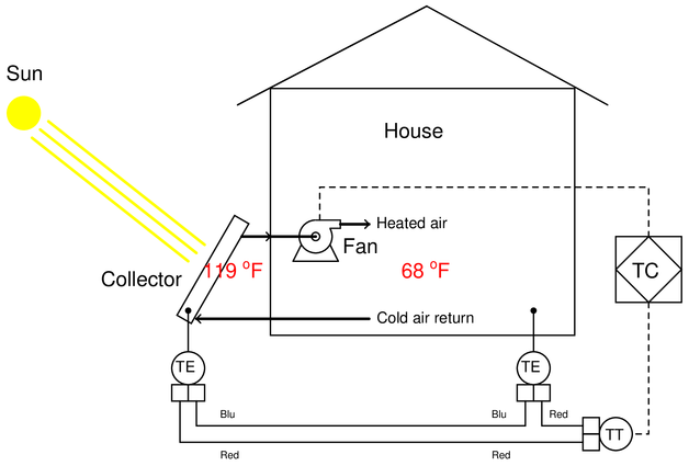
Answer the following questions about this subsystem:
{\bullet} Identify the thermocouple type used in this application, and determine whether or not this type is a good choice.
{\bullet} Calculate the voltage measured at the input terminals of the transmitter, and also determine whether or not this transmitter needs to be enabled for reference junction compensation.
{\bullet} Identify the meaning of the diamond-shaped PID symbol labeled “TC”.
These are type ‘T’ thermocouples, sending 1.174 mV to the transmitter’s input. Cold junction compensation (CJC) should not be enabled in the transmitter, because we want to measure the difference in temperature between the collector and the house, not compensate for one of those thermocouples’ voltages!
The diamond symbol is a logic device—most likely a PLC—used for on/off control of the fan.
Calculate the voltage sensed by the analog-to-digital converter inside the temperature transmitter:
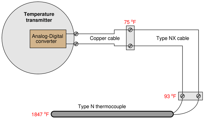
Voltage at ADC: $35.948~mV$
According to an ITS-90 table for type N thermocouples, the measurement junction will generate 36.577 mV at 1847 °F, while the reference junction (at the NX-copper cable junction) will generate 0.629 mV at 75 °F. Since we know these two junctions’ voltages are opposed to each other, the voltage seen at the transmitter terminals will be 35.984 mV.
Calculate the appropriate millivoltage values and potentiometer resistances to simulate a thermocouple at the desired temperatures, assuming the ambient temperature at the transmitter is 72 °F and the transmitter has cold junction compensation enabled:
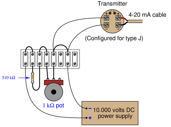
{\bullet} $T_{simulate} = 550~^{\circ}F$ ; $V_{input}$ =
{\bullet} $T_{simulate} = 300~^{\circ}F$ ; $V_{input}$ =
{\bullet} $T_{simulate} = 150~^{\circ}F$ ; $V_{input}$ =
{\bullet} $T_{simulate} = 550~^{\circ}F$ ; $V_{input} = 14.516~mV$ ; $R_{pot} = 741.39~\Omega$
{\bullet} $T_{simulate} = 300~^{\circ}F$ ; $V_{input} = 6.815~mV$ ; $R_{pot} = 347.80~\Omega$
{\bullet} $T_{simulate} = 150~^{\circ}F$ ; $V_{input} = 2.278~mV$ ; $R_{pot} = 116.20~\Omega$
Suppose you walk up to this thermocouple, installed to measure the temperature of an enclosed process vessel, and connect a sensitive voltmeter to the terminals at the junction head:
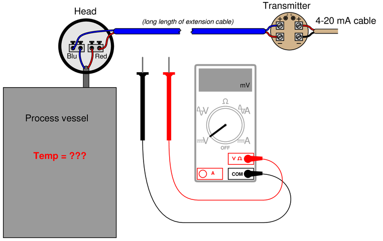
Determine the process temperature if you read 7.825 mV with the voltmeter connected to the screw terminals inside the thermocouple head. Assume a head temperature of 92 °F.
Suppose at some later time you connected the voltmeter to the transmitter’s input terminals and read 8.332 mV. Calculate the process temperature at this time, assuming an ambient temperature of 66 °F at the transmitter.
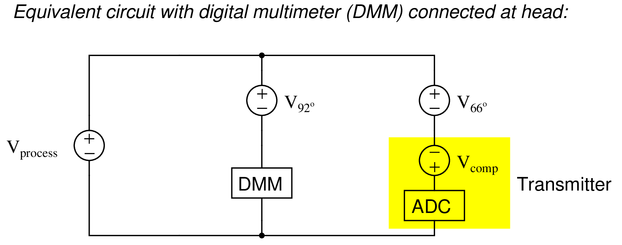
An equivalent circuit diagram shows the relationships between the thermocouple measurement junction (in the process), the two reference junctions formed where thermocouple wire meets copper wire, the digital multimeter, and the temperature transmitter (when the DMM is connected at the head):
$T_{process} = 388~^{\circ}F$ at 7.825 mV (measured at 92 °F head)
Another equivalent circuit diagram shows the relationships between the thermocouple measurement junction (in the process), the two reference junctions formed where thermocouple wire meets copper wire, the digital multimeter, and the temperature transmitter (when the DMM is connected at the transmitter):
$T_{process} = 385~^{\circ}F$ at 8.332 mV (measured at 66 °F transmitter terminals)
A type J thermocouple is inserted into a process, with a digital multimeter connected to its terminals. The ambient temperature at the DMM’s test lead connections is 17 °C. Calculate the thermocouple’s measurement junction temperature at the following millivolt measurements (rounding to the nearest degree Celsius):
{\bullet} 5.05 mV ; $T$ =
{\bullet} 17.82 mV ; $T$ =
{\bullet} 31.44 mV ; $T$ =
{\bullet} 40.29 mV ; $T$ =
All answers based on ITS-90 thermocouple table values:
{\bullet} 5.05 mV ; $T = 112~^{\circ}C$
{\bullet} 17.82 mV ; $T = 346~^{\circ}C$
{\bullet} 31.44 mV ; $T = 586~^{\circ}C$
{\bullet} 40.29 mV ; $T = 73~^{\circ}2C$
A type K thermocouple is inserted into a process, with a digital multimeter connected to its terminals. The ambient temperature at the DMM’s test lead connections is 84 °F. Calculate the thermocouple’s measurement junction temperature at the following millivolt measurements (rounding to the nearest degree Fahrenheit):
{\bullet} 2.55 mV ; $T$ =
{\bullet} 6.21 mV ; $T$ =
{\bullet} 10.93 mV ; $T$ =
{\bullet} 18.83 mV ; $T$ =
All answers based on ITS-90 thermocouple table values:
{\bullet} 2.55 mV ; $T = 195~^{\circ}F$
{\bullet} 6.21 mV ; $T = 357~^{\circ}F$
{\bullet} 10.93 mV ; $T = 567~^{\circ}F$
{\bullet} 18.83 mV ; $T = 904~^{\circ}F$
Suppose three different voltmeters are connected to a thermocouple, with each voltmeter having a different ambient temperature:
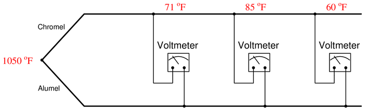
Calculate the amount of voltage registered by each of the three voltmeters, as well as answer the following questions:
{\bullet} If a fourth voltmeter were connected to this same thermocouple, would it affect the readings of the other three?
{\bullet} If a thermocouple transmitter were connected to this thermocouple, would it affect the readings of the voltmeters? Would it matter whether or not this transmitter were equipped with reference junction compensation?
Each voltmeter forms its own reference junction where the copper wires of each voltmeter connect to the chromel and alumel thermocouple wires. Each voltmeter’s reference junction produces its own voltage, opposed in polarity to the voltage of the measurement junction (at 1050 °F). This means we must perform a separate voltage calculation for each voltmeter based on each meter’s reference junction temperature. An equivalent schematic diagram shows how the four dissimilar metal junctions relate to one another, and to the three voltmeters:

The chromel and alumel wire types identify this as a type K thermocouple, and so we may use a type K thermocouple table to look up voltages for all four junction temperatures:
{\bullet} Type K at 1050 °F = 23.439 mV
{\bullet} Type K at 71 °F = 0.865 mV
{\bullet} Type K at 85 °F = 1.181 mV
{\bullet} Type K at 60 °F = 0.619 mV
Since we know the measurement and reference junctions stand opposed to one another in each voltmeter loop, we may calculate each voltmeter’s reading by subtracting the reference junction’s voltage from the measurement junction’s voltage for each voltmeter:
Voltage registered by the left-hand voltmeter (at 71 °F):
$$23.439~mV - 0.865~mV = 22.574~mV$$
Voltage registered by the center voltmeter (at 85 °F):
$$23.439~mV - 1.181~mV = 22.258~mV$$
Voltage registered by the right-hand voltmeter (at 60 °F):
$$23.439~mV - 0.619~mV = 22.820~mV$$
The voltage read by each voltmeter is a simple function of Kirchhoff’s Voltage Law, with the measurement junction and the voltmeter’s reference junction being the only voltage sources in the KVL loop. Therefore, connection of a fourth voltmeter will have no effect whatsoever on the other three voltmeters. Likewise, connection of a thermocouple transmitter to this same chromel/alumel wire pair will have no effect on the voltmeters’ readings, with or without reference junction compensation.
Calculate the amount of voltage “seen” by the voltmeter given the following measurement and reference junction temperatures:
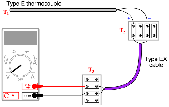
{\bullet} $T_{1} = 233~^{\circ}C$ ; $T_{2} = 31~^{\circ}C$ ; $T_3 = 25~^{\circ}C$ ; $V_{meter}$ =
{\bullet} $T_{1} = 348~^{\circ}C$ ; $T_{2} = 40~^{\circ}C$ ; $T_3 = 16~^{\circ}C$ ; $V_{meter}$ =
{\bullet} $T_{1} = -161~^{\circ}C$ ; $T_{2} =-4~^{\circ}C$ ; $T_3 = 23~^{\circ}C$ ; $V_{meter}$ =
{\bullet} $T_{1} = 836~^{\circ}C$ ; $T_{2} = 34~^{\circ}C$ ; $T_3 = 19~^{\circ}C$ ; $V_{meter}$ =
All answers based on ITS-90 thermocouple table values:
{\bullet} $T_{1} = 233~^{\circ}C$ ; $T_{2} = 31~^{\circ}C$ ; $T_3 = 25~^{\circ}C$ ; $V_{meter} = 14.395~mV$
{\bullet} $T_{1} = 348~^{\circ}C$ ; $T_{2} = 40~^{\circ}C$ ; $T_3 = 16~^{\circ}C$ ; $V_{meter} = 23.856~mV$
{\bullet} $T_{1} = -161~^{\circ}C$ ; $T_{2} =-4~^{\circ}C$ ; $T_3 = 23~^{\circ}C$ ; $V_{meter} = $-$9.039~mV$
{\bullet} $T_{1} = 836~^{\circ}C$ ; $T_{2} = 34~^{\circ}C$ ; $T_3 = 19~^{\circ}C$ ; $V_{meter} = 62.701~mV$
Note: all temperatures at $T_2$ are irrelevant because this is a junction between similar metals (type E wires connecting to corresponding type EX extension wires). The reference (cold) junction is where the type EX wires connect to copper, at temperature $T_3$.
Calculate the voltage across the bridge ($V_{AB}$) at the following RTD temperatures, assuming a 604 $\Omega$ nickel-iron RTD with an alpha value of 0.00518:
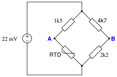
{\bullet} $T = 0~^{\circ}C$ ; $V_{AB}$ =
{\bullet} $T = 81~^{\circ}C$ ; $V_{AB}$ =
{\bullet} $T = -45~^{\circ}C$ ; $V_{AB}$ =
{\bullet} $T = 320~^{\circ}F$ ; $V_{AB}$ =
All answers shown here based on tabulated values for the RTD’s resistance (rather than values calculated by formula):
{\bullet} $T = 0~^{\circ}C$ ; $V_{AB} = -0.6989~mV$
{\bullet} $T = 81~^{\circ}C$ ; $V_{AB} = 0.9568~mV$
{\bullet} $T = -45~^{\circ}C$ ; $V_{AB} = -1.6215~mV$
{\bullet} $T = 320~^{\circ}F$ ; $V_{AB} = 2.4831~mV$
Suppose someone builds a dual-junction thermocouple circuit using type T thermocouple wire (copper and constantan metals), then measures voltage in the loop using a voltmeter:
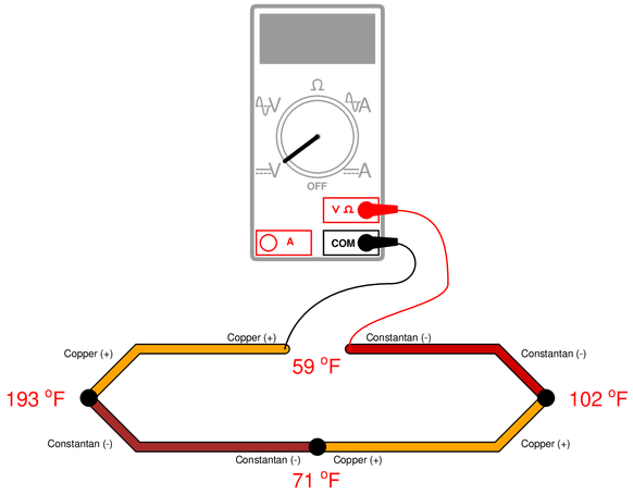
Calculate the voltage read by the voltmeter, using a type T thermocouple table to find millivolt potentials for each of the junctions.
The voltmeter should read $-3.908$ mV. Counting all the junction voltages (with polarities shown in reference to whether they match or oppose the meter’s test lead polarity):
{\bullet} 193 °F junction = $-3.789~mV$
{\bullet} 71 °F junction = $+0.857~mV$
{\bullet} 102 °F junction = $-1.565~mV$
{\bullet} 59 °F junction = $+0.589~mV$
{\bullet} Loop total voltage = $-3.908~mV$
Hint: any junction pushing conventional flow in a counter-clockwise direction is regarded here as a “positive” figure. Any junction pushing in a clockwise direction is regarded as a “negative” figure.
The last junction (at 59 °F) may be treated as a single copper-constantan junction because the metal type of the meter’s test leads acts as an intermediate metal. The fact that both the copper and constantan test lead junctions are at the same temperature allows us to disregard the test lead metal altogether and treat it as a single copper-constantan junction at 59 °F.
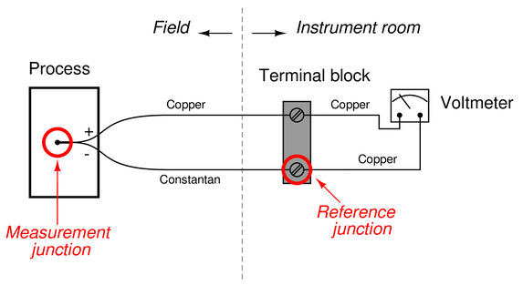
When a type “T” thermocouple (copper/constantan) is connected to a voltmeter made of copper wires, two active junctions are formed: one at the point of measurement (the measurement junction) and one at a terminal near the voltmeter (the reference junction). The copper-to-copper junction at the top screw of the terminal block is of no consequence because it is a junction of identical metals, and as such generates no thermoelectric voltage:
The amount of voltage sensed by the voltmeter in this thermocouple circuit is equal to the difference in voltages produced by the measurement and reference junctions:
$$E_{meter} = E_{meas} - E_{ref}$$
Now consider a type “J” thermocouple connected to a copper-wire voltmeter. Here we see there are not two but three active junctions of dissimilar metals:
Upon first observation it would appear this circuit is more complicated than the type “T” thermocouple circuit, owing to the existence of the additional dissimilar-metal junction. However, a principle called the Law of Intermediate Metals allows us to consider the two reference junctions (iron-copper and constantan-copper) as electrically equivalent to a single reference junction of iron-constantan, such that the type “J” thermocouple circuit becomes just as simple as the type “T” circuit with one measurement junction and one reference junction in opposition to each other.
Explain what the Law of Intermediate Metals is, and how it may be used to simplify the two active reference junctions of the type “J” circuit. Also, explain why it is important that the terminal block be isothermal in nature.
The Law of Intermediate Metals tells us that a series chain of dissimilar metal junctions at the same temperature are electrically equivalent to a single junction comprised of the outer two metals (ignoring all the intermediate metal types between) at that temperature. Thus, the iron-copper-constantan reference junction pair is electrically equivalent to a single iron-constantan reference junction, so long as both screw terminals are at the same temperature (isothermal). This principle renders the meter’s metal type irrelevant.
Suppose someone builds a dual-junction thermocouple circuit using type T thermocouple wire (copper and constantan metals), then measures voltage between the two junctions with a voltmeter:
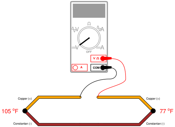
Calculate the voltage read by the voltmeter, using a type T thermocouple table to find millivolt potentials for each of the junctions.
The voltmeter should read -0.643 mV, because the 105 °F junction has a potential of 1.635 mV, the 77 °F junction has a potential of 0.992 mV, and the two junctions’ voltages are opposing one another in polarity with the positive terminal of the voltmeter connected to the negative-most copper wire.
Determine the temperature of the RTD, given $V_{CD}= 140.5~mV$ and $V_{EF} = 140.1~mV$:
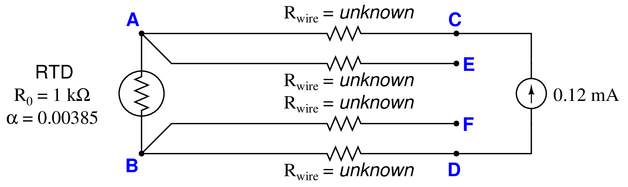
Assume a $1~k\Omega$ RTD with $\alpha = 0.00385$, and all wire resistances completely unknown (not assumed to be equal).
$V_{RTD} = 140.1~mV$
$R_{RTD} = 1167.5~\Omega$
$T = 43.5~^{\circ}C = 110.31~^{\circ}F$ (both values calculated from formula, not table)
Suppose you need to measure the temperature of an operating oven using nothing but a $1000~\Omega$ RTD ($\alpha = 0.00385$), a $1.75~k\Omega$ precision resistor, and a battery of unknown voltage:
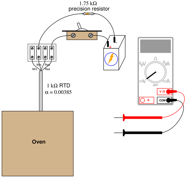
Turning the switch on, you measure 1.32 V across the resistor and 1.22 V across the RTD. Calculate the oven temperature based on these measurements, and also explain why it is important to quickly take these measurements once the switch is turned on.
$R_{RTD} = 1.617~k\Omega$
$T_{oven} = 160.4~^{\circ}C = 320.7~^{\circ}F$ (calculated from formula, not from a table)
The voltage measurements must be taken very soon after the switch is thrown to avoid measurement errors due to “self-heating” of the RTD.
Determine the temperature of the RTD, given a measured voltage of 89.2 mV between test points C and D, and 88.7 mV between test points E and D:
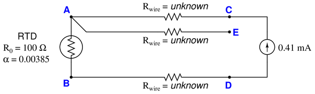
Assume a $100~\Omega$ RTD with $\alpha = 0.00385$, and all wire resistances to be equal to each other.
$V_{RTD} = 88.2~mV$
$V_{wire} = 0.5~mV$ (each current-carrying conductor)
$R_{RTD} = 215.12~\Omega$
$T = 309~^{\circ}C$ (from table)
$T = 299.02~^{\circ}C$ (from formula)
Determine the temperature of the RTD, given a measured voltage of $-59.7$ mV between test points {\bf C} and {\bf D} in this circuit:
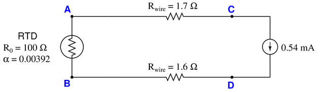
Assume a 100 $\Omega$ RTD with $\alpha = 0.00392$.
$R_{RTD} = 107.256~\Omega$
$T = 65~^{\circ}F$ (from table)
$T = 65.32~^{\circ}F$ (from formula)
Suppose you need to determine the temperature of a fluid inside a pipe. Installed in this pipe is a 2-wire $100~\Omega$ RTD inside a thermowell, not connected to a transmitter or any other circuit. You happen to have a multimeter with you to measure resistance at the RTD leads.
Touching the two test leads of your multimeter together, you measure $0.3~\Omega$. Then, connecting those same leads to the RTD’s wires, you measure $184.6~\Omega$. You do not happen to have an RTD table with you, but you do carry a calculator.
Calculate the approximate temperature of the fluid in this pipe, assuming the most common $\alpha$ value for $100~\Omega$ RTDs.
The $\alpha$ value is most likely 0.00385, resulting in a calculated temperature of 218.96 °C or 426.13 °F.
Published under the terms and conditions of the Creative Commons Attribution License

by Munir Ahmad

by Munir Ahmad