An electromechanical relay is an electrical switch actuated by an electromagnet coil. As switching devices, they exhibit simple “on” and “off” behavior with no intermediate states. Relays are very useful devices, as they allow a single discrete (on/off) electrical signal to control much greater levels of electrical power, and/or multiple power or control signals that are otherwise isolated from each other. For example, a relay may be controlled by a low-voltage, low-current signal that passes through a delicate switch of some sort (e.g. limit switch, proximity switch, optical sensor), and then the switching contacts of that relay may be used to control a much higher-voltage, higher-current circuit, and even multiple circuits given multiple sets of switching contacts.
The electronic schematic symbol for a simple single-pole, single-throw (SPST) relay is shown here:
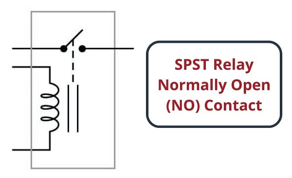
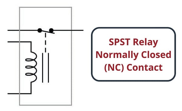
A coil of wire wrapped around a laminated ferrous core provides the magnetic field necessary to actuate the switch mechanism, energized by either AC or DC voltage, depending on the model. This electromagnet coil’s actuating influence on the relay’s contact(s) is represented by the dashed line. This particular relay is equipped with normally open (NO) switch contacts, which means the switch will be in the open (off) state when the relay coil is de-energized. Recall that the “normal” status of a switch is the resting condition of no stimulation. A relay switch contact will be in its “normal” status when its coil is not energized. A single-pole, single-throw relay with a normally-closed (NC) switch contact would be represented in an electronic schematic like this:
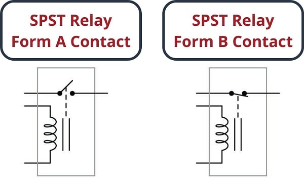
In the electrical control world, the labels “Form-A” and “Form-B” are synonymous with “normally open” and “normally closed” contacts, respectively. Thus, we could have labeled the SPST relay contacts as “Form-A” and “Form-B,” respectively:
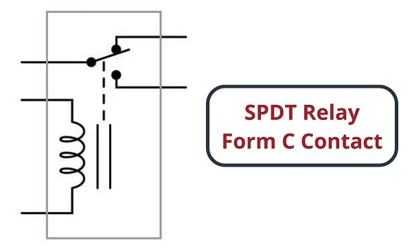
An extension of this theme is the single-pole, double-throw (SPDT) relay contact, otherwise known as a “Form-C” contact. This design of switch provides both a normally-open and normally-closed contact set in one unit, actuated by the electromagnet coil:
A further extension on this theme is the double-pole, double-throw (DPDT) relay contact. This design of switch provides two sets of Form-C contacts in one unit, simultaneously actuated by the electromagnet coil:
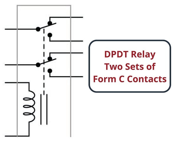
DPDT relays are some of the most common relay form types found in industry due to their versatility. Each Form-C contact set offers a choice of either normally-open or normally-closed contacts, and the two sets (two “poles”) are electrically isolated from each other so they may be used in different circuits.
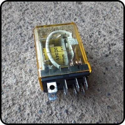
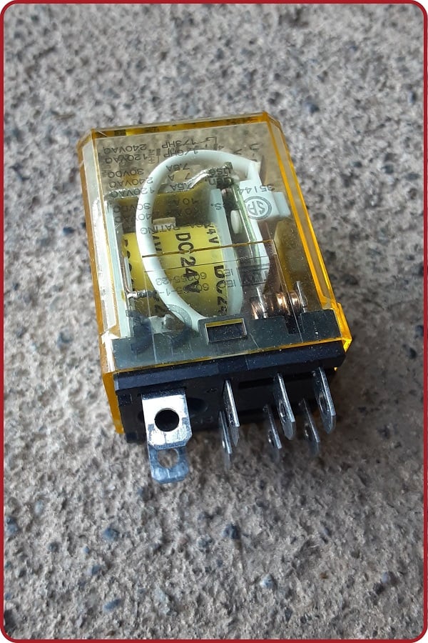
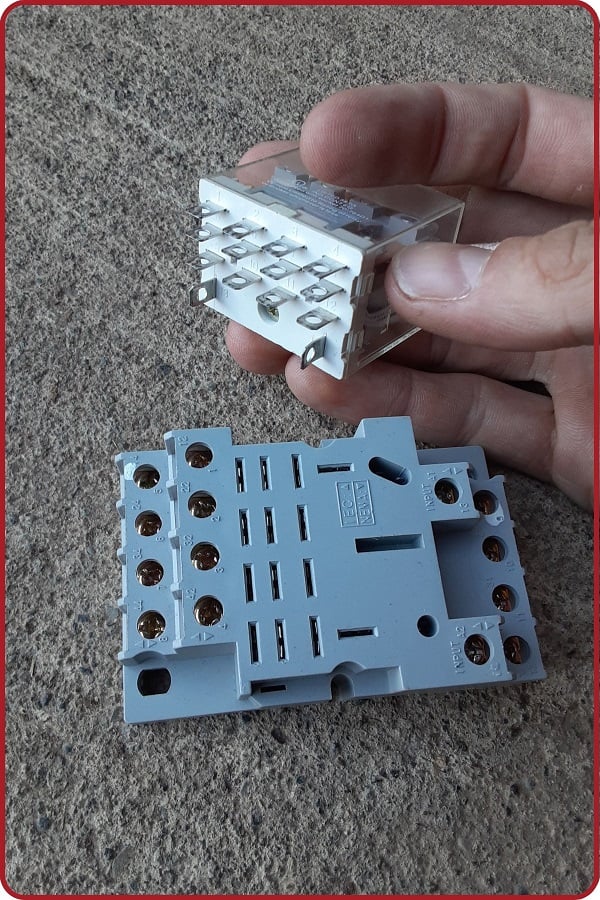
Two common packages for industrial relays are the so-called octal relay and the ice cube relay. These relays plug into multi-pin base sockets for easy removal and replacement in case of failure, and typically contain clear plastic cases allowing inspection of the working elements. A DPDT octal relay is shown in the following photographs, ready to be plugged into its base and then with the plastic cover removed to expose both sets of Form-C contacts:
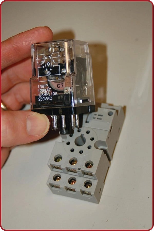
These relays connect to the socket with eight pins: three for each of the two Form-C contact set, plus two more pins for the coil connections. Due to the pin count (8), this style of relay base is usually reserved for DPDT connection style.
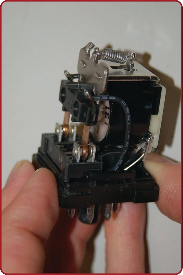
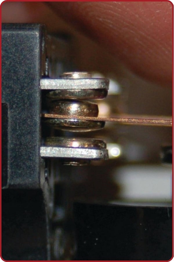
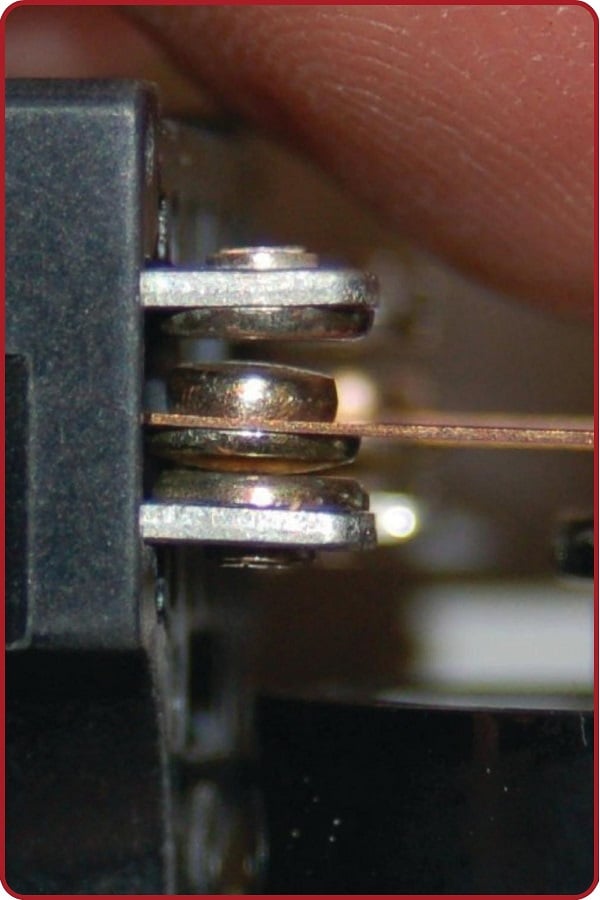
A closer view of one Form-C contact shows how the moving metal “leaf” contacts one of two stationary points, the actual point of contact being made by a silver-coated “button” at the end of the leaf. The following photographs show one Form-C contact in both positions:
The “ice cube” relay is functionally identical, but the pins are arranged in a rectangular pattern, rather than circular around the base. These relays can be found in single and double-pole varieties, and even up to 4 contact sets (4PDT) is fairly common. The below images show a standard From-C DPDT ice cube relay followed by a 4PDT with the matching socket.
Industrial control relays usually have connection diagrams drawn somewhere on the outer shell to indicate which pins connect to which elements inside the relay. The style of these diagrams may vary somewhat, even between relays of identical function. Take for instance the diagrams shown here, photographed on three different brands of DPDT relay:
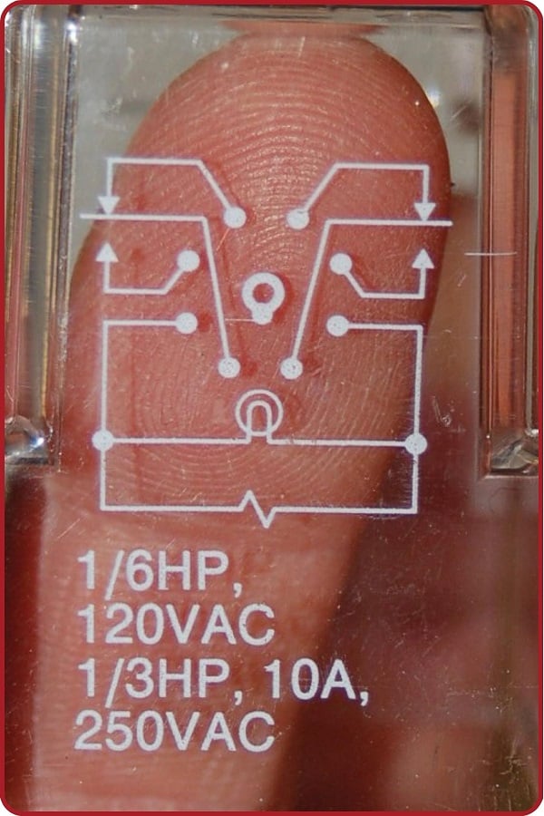
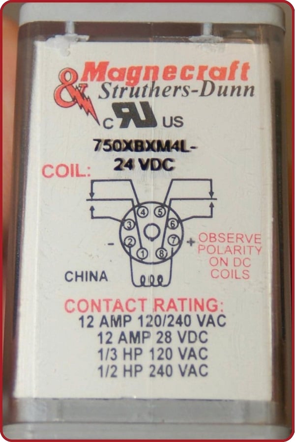
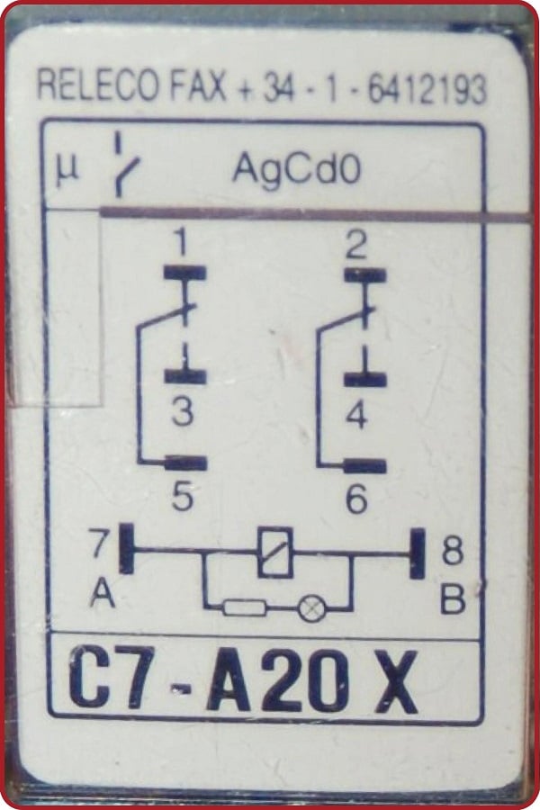
Bear in mind that these three relays are identical in their essential function (DPDT switching), despite differences in physical size and contact ratings (voltage and current capacities). Only two of the three diagrams shown use the same symbols to represent contacts, and all three use unique symbols to represent the coil.
REVIEW: