Facebook
 Google
 GitHub
 Linkedin
Info Byte: The Mystery of Ice Cube Relays–Coil Polarity
Relay and other coil devices pose a few confusing questions: How can the relay still work if you connect a DC supply in reverse? How can an alternating voltage attract and hold the load consistently?
Relays and other inductive coil-based devices are commonplace throughout every control system. Most of the time, we connect them and forget them—they just seem to work properly for many, many years. But if we stop and think about the operating principle behind magnetic fields, we find a few confusing questions that we can either attempt to understand or simply ignore.
My problem is that when I run across these concepts, I feel the urge to investigate until I understand.
Check out our exclusive ebook: The Complete Guide to Relays!
Mystery #1: Does DC Coil Polarity Matter?
The answer to this question depends on the type of relay, but for the mysterious part of the answer, we’ll consider using only a standard DC ice cube relay with no protective add-ons or LED indicators.

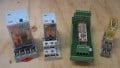
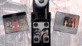
Figure 1. Standard 24 volt DC coil relay in the ‘ice cube’ style.
These add-ons, which include flyback diodes and MOVs in addition to LED status indicators, can be attached with polarized or keyed connectors. This forces the technician to install the device correctly or risk failure.
However, for a general-purpose DC relay, the coil is labeled as 5, 12, or 24 volts, and the wiring diagram often lacks the positive (+) and negative (-) symbols. It can be proved through trial and error that no matter which way you connect the DC supply, the relay will successfully energize and switch the contacts.
Magnetic Fields: Opposites Attract
I was initially concerned with this observation. In previous experience, when you create an electromagnetic field by passing an electrical current around a ferrous core, the magnetic field will create a specific north and south pole, according to the right-hand rule of any physics text.
If the current around a coil is reversed, so is the polarity of the magnetic field.
If you place the metallic load (switch contacts or solenoid valve plunger) into this magnetic field, it will be attracted against the normal return spring when energized.
If the supply wires, and therefore the magnetic field, were reversed, shouldn’t the load be pushed further away instead of pulled into position?
The answer to this mystery is to consider the load device, in this case, the contact set or the plunger. This object is made out of ferrous metal, containing iron. It is not a permanent magnet. A permanent magnet contains a predetermined north and south pole, often labeled on the magnet itself, like a compass dial.

Figure 2. In a classic science project example, a nail is wrapped with a wire and DC voltage is applied. The nail will attract iron filings to demonstrate the creation of an electromagnetic coil. Image used courtesy of Canva
This ferrous metal in the moving component is not locked in place—the polarity aligns when the magnetic field is energized. The moment that happens, the ferrous elements align themselves to be in attraction to the field, no matter which pole of the energizing field presents itself.
In this way, the switch contacts or plunger will be attracted against the spring force when the magnetic field is applied, no matter the polarity.
However, please note that a schematic should dictate how the device is wired. Knowing the physics does not give permission to connect the device incorrectly, which can damage other add-on devices or series control elements.
Mystery #2: Why Does an AC Coil Not Switch On and Off Constantly?
According to our previous answer, it would make sense that a coil supplied with AC voltage would attract the contact set regardless of polarity.
However, AC voltage in a field device presents a new problem.
Every half-cycle (which is either 120 or 100 times per second for 60/50 Hz voltage), the voltage will drop to 0 volts, then again begin to rise. Even with the phase shift of the inductive core, the constant lowering of the voltage would lead the engineer to believe that the attracting force will repeatedly fade away, possibly allowing the spring to return the contact set to normal before it attracts once again, assuming the device is small and quick enough to respond.
The results of this would be a disaster. Not only would the relay chatter loudly, but the lifespan would be severely decreased and the slight open and close of the contacts would arc and spark without relief.

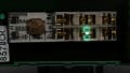
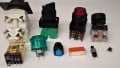
Figure 3. Industrial AC relays can be energized with 12 (shown above), 24, 120, or 220 volts AC, depending on the model. Even contactors with AC coils follow the same physical operation. Image used courtesy of Canva
So how does the AC coil work to prevent the rapid chattering of the opening/closing contacts as the voltage crosses zero every half-cycle?
Phase Shifting in AC Inductive Circuits
In many AC devices, the primary coil provides the holding force necessary to move the contact set or plunger. A portion of the coil is designed with a shielding ring of copper, usually around the edge of the coil. This is referred to as ‘shading’ a portion of the coil, just like shade would block light and heat energy.
The result of this ‘shading’ on the coil is a slight phase shift of just a portion of the magnetic field from the inductor. The timing offset ensures that the magnetic field, caused by the current, never drops away entirely, thus preventing noise and chatter from the contact or plunger.
This shading concept is also used in ‘shaded pole’ single-phase motors, which use this same slight phase shift to ensure that the motor begins rotating in a consistent direction (CW or CCW). This negates the need for a capacitor and centrifugal switch to open once full rotation speed is reached, like those used in a split-phase capacitor-start motor.

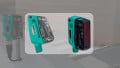
Figure 4. A classic AC coil ice cube relay with a 220/240 AC operating voltage. Image used courtesy of Canva
Electromechanical Devices in Control Circuits
Without a doubt, the concept of motion driven by magnetic fields, which are created by electrical current, is absolutely the most common method of supplying energy to drive load devices.
It’s easy to take field devices for granted while machines are running. However, taking the time to understand the science can greatly aid in both diagnosing failures and quickly returning the machines to service and can even prevent future breakdowns by employing the correct devices for each situation.
Love relays? So do we! Check out our whole collection of relay content:
- Differences Between Electromechanical and Solid State Relays
- How to Troubleshoot Mechanical Relays
- Info Byte: What’s the Reason Behind Relay Terminal Numbering?
- Info Byte: Preventing Relay Burnout with Flyback Diodes
- Understanding the Differences Between Protection Relays vs Control Relays
- I/O Module Debate: Digital Output or Relay Output?
- Contactors versus Relays - Differences and Applications
Related Content