Facebook
 Google
 GitHub
 Linkedin
Active Power, Reactive Power, Apparent Power, and the Role of Power Factor
The diverse power terms in electrical generation systems include active, reactive, and apparent power, all of which lead to the introduction of ‘power factor’ effectiveness in an AC circuit.
The diverse power terms in electrical power systems include active, reactive, and apparent power, all of which lead to the introduction of ‘power factor’ effectiveness in an AC circuit. AC circuits transfer energy to resistive and reactive loads and, in the case of purely resistive loads, the energy is dissipated in the same way direct current dissipates energy in a resistor.
Active power comes from DC or the resistive part of AC circuits when the voltage is in phase with the current, measured in Watts.
Reactive power comes from the capacitive or inductive parts of an AC circuit, when the voltage lags behind or leads the voltage, measured in VAR.
Apparent power is the right-triangle combination of active and reactive power, expressed in VA.
What is Power?
We must begin by understanding electric power in the first place: the rate at which energy is transferred to or from a part of an electric circuit. In an electrical circuit, the power is equal to the voltage difference across the element times current \(V \times I\). The power is measured in watts \(1W=1J\)/\(s\)
$$Electric~Power = Voltage \times Current$$
$$P = V \times I$$
$$P = I^2 \times R$$
$$P = \frac{V^2}{R}$$
These equations are derived from Ohm’s law which is \(V = I\times R\) where V = Voltage or potential difference in the circuit, I = current, and R = Resistance in the circuit.

Figure 1. Measuring AC current is a major component of verifying power generation and dissipation in large loads. Image used courtesy of Canva
Instantaneous Power
Instantaneous power means the power at any instant of time or the power at any given moment of time and can be written as:
$$P (t) = V (t) \times I (t)$$
In a DC circuit, the power required for a voltage V to force a current I through a circuit is equal to V times I. Similarly, if the alternating current is passed through the circuit, the power required at each instant is equal to the value of the voltage at that instant times the current at the same instant. In the practical world, loads are the combination of resistive, inductive, and capacitive elements at the consumer end.
There are Three Types of Loads
1. Resistive Load: where V and I are in phase and the power is always positive like braking resistors, heaters, and light bulbs.
2. Inductive load: current lags by voltage like motors, fans, and transformers.
3. Capacitive load: current leads by voltage (few examples of pure capacitive loads).
The phase-angle difference between the current and voltage has an important effect on the power supplied, as the instantaneous voltage corresponding to any particular instantaneous current depends on the angle between them. Therefore, in the alternating current circuits power cannot usually be obtained simply by multiplying the effective voltages and effective amperes as was done in the case of DC. The effect on the power of the difference in phase angle between the current and voltage must be taken into account.
Types of Power:
1. Active Power (kW, MW, GW)
2. Reactive Power (kVAR, MVAR)
3. Apparent Power (kVA, MVA)
Figure 2 describes the famous example to understand the difference between the three powers. The glass filled with cocktail represents the true power and the frothy foam on the top is reactive power and the sum of active and reactive is apparent power in the system.
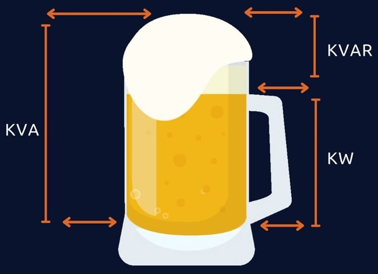
Figure 2. A famous analogy to describe active, reactive, and apparent power
Active Power or Real Power
Active power is often called real, actual, true, or useful power. In DC circuits, power is simply the voltage across the load times current flowing through it because in DC circuits there is no phase angle between the voltage and current therefore no power factor in DC circuits. In other words, the voltage and current are in phase with each other, meaning the voltage and current start at the same time, reach a peak, and then again touch zero at the same time.
$$P = V \times I~for~DC~circuits$$
Whereas in AC circuits, there is a phase angle between voltage and current expressed with the added component of \(cos \theta\).
In a single-phase AC circuit, active power is:
$$P=V \times I\times cos\theta$$
In a 3-phase AC circuit:
$$P = \sqrt{3} \times V \times I\times cos\theta$$
In Figure 3, the current and voltage are in phase with each other making a +90 degree angle at the same time and the positive voltage times positive current generates positive power. When both current and voltage are negative, the power is still positive therefore in both cases the power is always positive this is called active power. The power curve will lie entirely above the horizontal axis and reflects that all of the work done is positive.
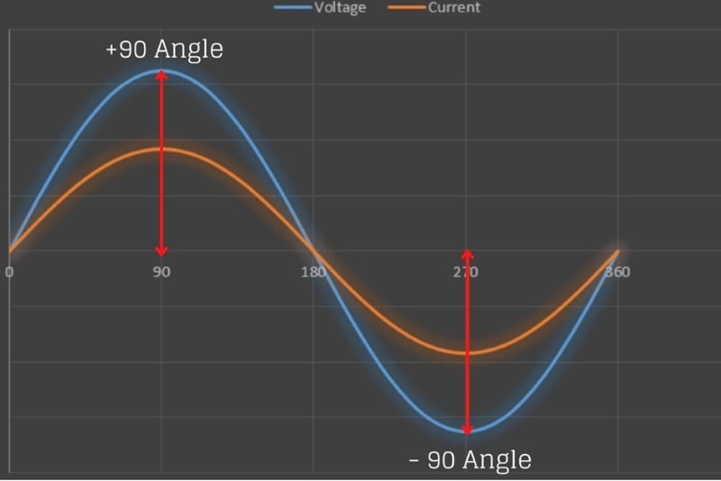
Figure 3. Current and voltage are in phase with each other
The real power (also called useful power or watt-full power) actually does the real work in the circuit and always flows from source to load or is supplied to the load from the generator all of the time as in Figure 4.
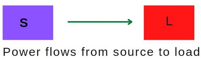
Figure 4. Active power flows from source to load
Features of Active Power:
- The active power is always positive and does not change its direction, always flows from source to load.
- Denoted by P and measured in watts (kW, MW, GW).
- Measure using a wattmeter.
- Active power produces heat, mechanical power, and light.
Reactive Power
Reactive power occurs in AC circuits when voltage and current are not in phase. Its unit is VAR (voltage ampere reactive). In the real world, loads are a combination of resistive, inductive, and capacitive elements and it is impossible to determine the nature of the load (small/large, domestic/industrial inductive/capacitive). There are two types of reactance:
- Capacitive Reactance (negative)
- Inductive Reactance (positive)
The power can be positive and negative. When the power is flowing from source to load then it's positive, and the power is flowing from load to source then it’s called negative power. In general, reactive power is only defined for AC circuits and continuously bounces back and forth between source and load and is symbolized with the letter Q as in Figure 5.
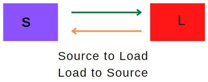
Figure 5. Reactive power flows from source to load and back to the source
Reactive Power (Q)
$$Q = V \times I \times sin\theta$$
Features of Reactive Power:
- Changes its direction periodically and it is positive and as well as negative.
- Donated by letter “Q” and measured in VAR, KVAR, MVAR
- Measured using VAR meter.
- Transformers and induction motors use reactive power to produce a magnetic field.
Transformers also need reactive power to generate a magnetic field in the primary coil and induce a voltage in the secondary coil. Therefore, if the reactive power supply is not adequate, the transformer will not transform voltages and the motor will not rotate. The synchronous alternators also generate or absorb reactive power depending upon DC excitation to its field winding. When the generator is over-excited it generates the reactive power and absorbs reactive power when the generator is under-excited.
Apparent Power
This power is the combination of active and reactive power and is expressed in volt-ampere or kilovolt-amperes (kVA).
In fact, most of the loads in our routine daily life (electric fan, electric iron, induction motor) are a combination of resistive & inductive loads. The resistive load consumes active power and the inductive load consumes reactive power and the total power delivered by the source is the combination of active & reactive power is called apparent power.
Apparent Power (S):
$$S^2 = P^2 + Q^2$$
Where S = Apparent Power measured in kVA, Q = Reactive Power in kVAR and P = Active Power in kW
Features of Reactive Power
- Apparent is the sum of active and reactive power.
- Donated by letter “S”
- Measured in VA, kVA, and MVA
Power Triangle
The relationship between powers can be represented in the form of vectors called the “Power Triangle”. The active power is represented as horizontal whereas reactive power is shown as a vertical vector and the apparent power connects the active and reactive vectors. If the angle “θ” between active and apparent power increases, the reactive power increase.
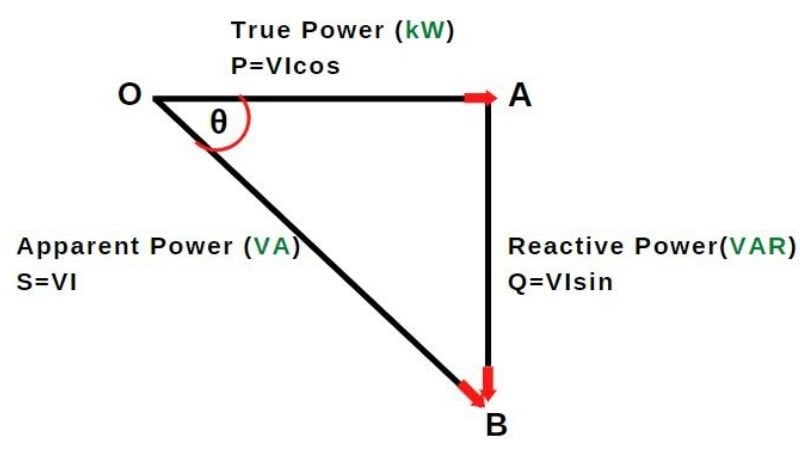
Figure 6. The power triangle describes the relationship between active, reactive, and apparent power.
Power Factor
The power factor is an important concept in an electrical system and a good power factor determines the design quality and effective use of the supply in the electrical system. It shows the relation of the real power to the apparent power and is simply the ratio of active (real) power in watts to apparent power in volt-amperes.
$$Power~Factor = \frac{Active~Power}{Apparent~Power}$$
A power factor of 1.0 is called a “unity power factor” or 100 percent power factor, which means that the current and voltage is “in phase”. It is impossible to obtain a 100% power factor at all parts of a power system. In transmission lines, high PF is necessary which reduces transmission losses and is also better for an inductive load-like motor to run efficiently and avoid overheating.
The question is: what does the power factor actually indicate? Suppose the power factor is 0.8. This means that, out of 100%, the system is consuming 80% of active power and 20% is reactive power. This is the significance of the power factor that indicates the total amount of active power in the system. The power factor is an important term in an AC power system if the voltage and power of the system are constant then the power factor is inversely proportional.
$$Line~Current \propto \frac{1}{Power~Factor}$$
The expression of three-phase power is written as:
$$P = \sqrt{3} \times V \times I \times cos\theta$$
Therefore
$$I = \frac{P}{\sqrt{3} \times V \times cos\theta}$$
Here the factors \(P\), \(\sqrt{3}\), and \(V\) are taken as constants, therefore current is inversely proportional to \(cos \theta\) i.e. \(I \propto 1\) / \(cos \theta\). This means that if the power factor of the system is low, the current of the system becomes large.
Disadvantages of Low Power Factor in a System
- If the power factor of the system is lower, the system's current becomes large.
- Large KVA rating of the equipment: alternators, transformers, and switchgear are rated in KVA as we know that \(KVA=KW\)/\(cos \theta\), which means that if you need desire power in KW from the machine, the KVA of the machine needs to be higher. Therefore, to increase the current carrying capacity of the machine, the cross-section conducting parts of the machine has to be made larger which makes the machine larger, heavier, and more expensive.
- Greater conductor size: At the low power factor for transmitting the same quantity of power larger cross-section of the conductor is required. This is because, at low power factor conditions, more current is required to fulfill the useful power demand of the consumer.
- Large copper losses: As we already know that current is inversely proposal to the power factor, therefore if the power factor of the power system is low, the current will increase. \(I \propto 1\)/\(PF\). The line losses increased by \(I^2 \times R\) which results in lower efficiency of the system.
- The low lagging power factor causes a high voltage drop in alternators and transformers.
Power Factor Lagging vs Leading
In the power network system, reactive power can be increased and decreased using system excitation. If excitation increases, it means flux increases and consequently reactive power will increase. When reactive power increases power factor lagging (decreases). The lagging load consumes reactive power and the generator will supply reactive power to the system.
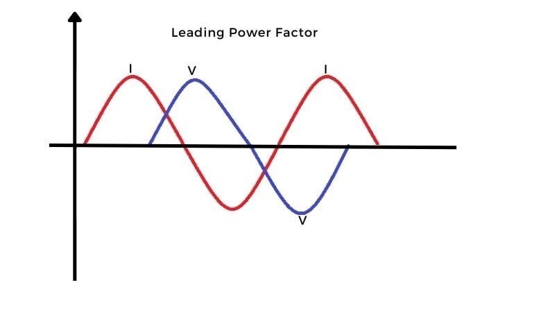
Figure 7. Visualization of ‘leading’ power factor.
Let’s look into another way when the voltage decreases, excitation decreases which means flux decreases and consequently reactive power will decrease, and hence power factor leading (increases). The generator consumes reactive power from the load. This reactive power is used to build the magnetic field required by the generator to work properly. So we can say that over-excited synchronize machine acts as a capacitor and under-excited synchronize machine acts as an inductor.
It has become the practice to say that the power factor is lagging when the current lags the supply voltage and leading when the current leads the supply voltage.
Power Factor Effect on a System
Active power is useful power that does some real work in an AC circuit, whereas reactive power is non-useful power that flows back and forth (in both directions from source to load) but produces electric or magnetic flux. Apparent power is total power in the system and is a combination of active power and reactive power and measured in KVAR. Large industrial types of equipment like transformers rating are mentioned in KVA. The lower the power factor, the larger the size of the source to generate that power which results in the cost of generation and transmission of the electrical energy.
Need to learn more about power in generation systems?
- Understanding Power Quality, Monitoring, and Correction
- Duties of Power Plant Operators, The Journey From Entry to Senior Operator
- Handling of Power System Data | Indications, Counters, and Data Flags
- Inrush Current: Why Is Motor Startup Current So High?