 Facebook
 Google
 GitHub
 Linkedin
Grounding for Control Transformers
Grounding transformer connections presents its own set of challenges. This article addresses these challenges and several common configurations for control transformer grounding.
Any electrical control equipment schematic reveals a large number of bonded ground connections. Many of the connections are obvious, such as different control cabinets, different electrical supply lines, etc. But an often confusing point arises with the many ground connections associated with transformers.
Transformers exist within nearly every power delivery system and in most control systems as well. They are used often with three-phase electrical supply mains to provide a single phase of 240V or 120V (often both) for the use of loads such as heaters, DC power supplies, and other plug-in equipment.
The transformer is a complex device and often includes specific connection details which are not obvious but fortunately often included in schematics.
In this article, the specific detail of grounding connections to a transformer will be investigated, as well as several common configurations of grounding connections. Every piece of equipment is different, so this will not address every situation, but should provide clarity and reasoning why so many ground connections exist.
Why is a Transformer Connected to Ground?
Although the purpose and fundamentals of ground has been extensively discussed in previous articles, it is worth mentioning again at a very broad level.
Ground connections provide a redundant safety conduit, interlaced between every piece of equipment and metallic object that may come into contact with electricity.
If, for reason of failure or improper wiring, an energized wire comes loose and touches anything metal nearby, a free-flowing low-resistance circuit will be established. The resulting large current should ideally trip a breaker or blow a fuse almost immediately until the problem is resolved and the circuit reset.

Figure 1. A control transformer is part of this linear power supply circuit, clearly showing the soldered connection terminals for the primary and secondary windings, as well as a firmly grounded metal-to-metal base.
Since the failure can come from nearly any metallic object near an energized wire, it seems logical to examine every point in and around every circuit to ensure that it is properly grounded.
Typical Transformer Grounding Points
There are almost always three points of bonding to ground, with a rare exception of two, as discussed later. Those three points are: the primary winding, the chassis itself, and the secondary winding.
Primary Winding to Ground
Most often, the primary winding of a transformer in a control system is supplied from a three-phase or higher voltage single-phase source. If wired properly, this incoming supply line has already been connected to ground when it entered the facility or control cabinet.
Therefore, it is not common to see a grounding symbol attached to the schematic right at the input primary winding, but be sure to trace it back to the source to ensure that it has, in fact, already been grounded.
Transformer Chassis to Ground
Nearly every transformer chassis is constructed out of metal, though some small ones are plastic. If the casing is metal, it should not carry any voltage. The purpose of the transformer is to keep all electrical conduction contained to the wires around the coils — none of the electricity should flow into the ferrous core or the metal chassis surrounding the coils.
In the case of failure due to a broken wire however, that chassis may become energized, and if it does, it is connected to a nearly zero-resistance electrical path. It is critical that the metal case of the transformer be firmly bonded to ground, not just the primary wiring.
Secondary Winding to Ground
One of the benefits of a transformer is that it provides isolation between the incoming and outgoing lines, even if there is no voltage change. The core does not conduct electricity, so although it induces an appropriate voltage at the side of the output, that output wire will never have any physical connection to the main supply input.
In terms of grounding, this means that the secondary output must be grounded, since it is another isolated part of the circuit. Any wiring failure downstream from the transformer must have a way to re-enter the circuit briefly in order to trip that circuit protection device. As with any supply, it is the Neutral wire which is bonded to ground, and this will happen just after the output of the transformer.
Grounding in Common Transformer Wiring
Transformers come in different wiring configurations. While not all of these are covered in this article, it helps to understand the most common: single output and dual output.
Single Output Voltage
If the transformer has one single voltage output, it is likely to be either 240V or 120V to provide power for loads, or it could be 24V AC, which is common for many control devices.

Figure 2. A single output voltage allows one of the two wires to be bonded to ground, and therefore is the neutral wire.
In either case, one of the two wires should have a connection to ground. This wire becomes the neutral wire. If there is only a single output voltage, it does not matter which wire is neutral and grounded, although sometimes a particular one will be preferred in order to maintain phase alternation between devices.
It is here with the single output transformers in which sometimes, but very rarely, there will exist a secondary winding that is ungrounded. This is only installed in order to prevent any sort of electromagnetic noise from traveling through ground near the output.
This is usually only connected in this manner when testing and troubleshooting equipment using grounding bench test devices such as oscilloscopes.
If the secondary of the transformer were grounded, in addition to the device under test, a ground loop may occur and cause damage. These are special variations of isolation transformers.
Dual Output Voltage
It is often the case that a transformer supplied with a higher voltage will output two different levels of voltage. Most commonly this is a 120V/240V output. Three lines will exit the secondary winding — one at each end of the winding and one from the center, called a center tap.
Two different strategies exist for using this center tap wire.
First, if that center tap is connected to ground, it is called the neutral. If a load device is connected to the two outside wires, it will receive 240V. If a load is connected between one of the outsides and that center neutral, it will only receive 120V.
This way, there are two ways to achieve 120V (line to neutral) and one way to get 240V (line to line). This is the normal configuration for household wiring, as it allows very deliberate control of load circuits.
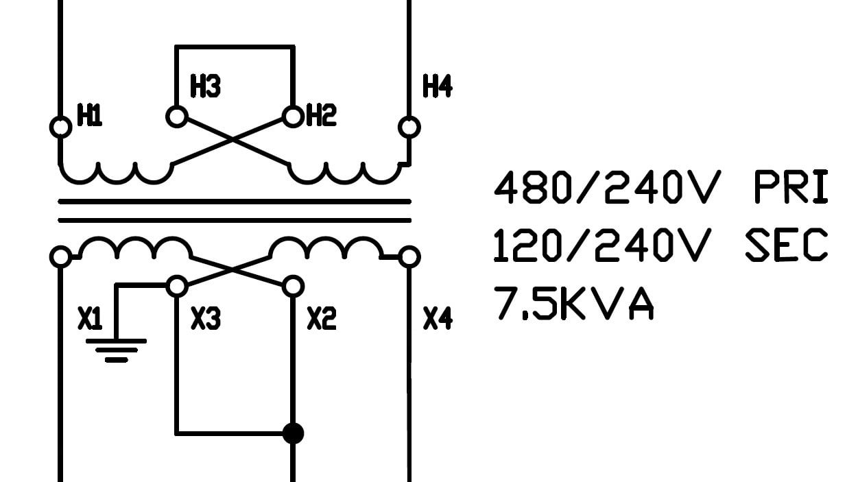
Figure 3. The first strategy in which the center tapped wire is connected to ground, making it the neutral. Line-to-line provides 240V, and either line to neutral provides 120V.
The second strategy consists of grounding one of the outside wires, making it the neutral. A load connected between the center tap and that outside neutral, it will receive 120V.
If the load is connected from outside to outside, it will receive 240V. In this manner, the voltage outputs are the same, but the lower and higher voltages are both confined to a single output wire, allowing for very deliberate control.

Figure 4. The second strategy bonds one of the outside wires to ground, making it the neutral. Center to neutral provides 120V and outside to neutral provides 240V.
Review of Control Transformer Grounding
Transformers are common devices, but the connections and operations can sometimes be confusing. Often, they are simply connected to a control circuit with hopes of correct operation but without clear understanding of the operation.
For most industrial controls, it would be typical to ensure a solid grounding connection on the primary winding side, as well as on the chassis itself. The secondary winding should also be bonded ground, adopting the most appropriate case for the particular equipment.
Want to learn more about grounding and power in control systems? We have plenty more!
- Fundamentals of Grounding in Automation Control Systems
- The Importance of Grounding Equipment for Safety
- Understanding Differences Between Power and Ground Side Switching
- Grounding DC Power Supplies
- Negative Effects of Grounding (Earthing) a DC Power Supply
- The Difference Between Ground and Neutral Conductors in Control Wiring
- The Importance of Neutral Wire in 3-Phase Systems
All images used courtesy of the author.
Related Content


A simple guideline I’d give is that the primary side should follow the *grounding rules of the upstream supply*, and a transformer earth terminal should connect to the protective earth of the supply. The secondary side ground strategy can be chosen to suit the specific installation. TN-S is probably a good default, with a “earth” point specific to the control cabinet.
I wouldn’t normally consider the split configuration for a control circuit but it has one potential fringe benefit, the earth leakage currents of mains filters will cancel which may be useful if a significant number of switch mode power supplies are supplied from the control transformer.