Facebook
 Google
 GitHub
 Linkedin
Fundamentals of Grounding in Industrial Automation and Control Systems
The subject of grounding in electronics is broad and complex, spanning across a variety of functions and objectives. In this article, we will investigate the applications and regulation of grounding in control systems on a fundamental level.
The subject of ground has a variety of meanings. Within the scope of electrical systems, not only are there different definitions, but each field of study uses grounding to accomplish different outcomes. In some cases, it is used to ensure the safety of people and equipment. Other times, it can enhance signal clarity for digital communications. What’s more, ground can even be a reference to conductors that carry current from load devices

Figure 1. A common ground point on the frame of a CNC machine. The green wires and ground symbol are typical of machine grounding (bonding).
It is safe to say that nobody can be an expert in all fields of electronics or have a thorough working knowledge of every regulation and code defining the scopes and purposes of ground connections. However, in this article, we will define several of the categories of ground use, along with some common applications, paving the way for a further specific understanding of some of these key areas.
What is Grounding?
When most people talk about grounding, they imagine the context of grounded outlets and green ground wires between machines, and rightly so. Power distribution holds most true to the original definition of ‘ground’.
In other places in the world, the idea of ground (called 'earthing') was a long stake driven into the ground outside a facility or residence and again at various places like power poles, substations, and so on.
Inside the facility or residence, anything metal is ideally connected to that vast large earth-ground connection—even devices plugged into outlets. The whole point of this ground system is that if any live, active voltage somehow touches anything metal, either directly or through water, skin, or another conductor, then a path is provided immediately to the nearest point back into the system. This network of interconnected wires not only provides a path in the case of active voltage failures, but it also causes every object to have the same voltage potential.

Figure 2. A grounding terminal block attached to a DIN rail on a machine.
The terminal block shown in Figure 2 has an exposed metal base clamped to the metal DIN rail providing a connection to the rest of the machine.
Grounding for Safety and Signal Conditioning
Grounding is usually grouped into two main areas: personal safety and signal conditioning. The rules surrounding usage are dictated somewhat by which category the situation requires.
The first category is grounding for equipment and personal safety. This category includes all residential and industrial machinery connections and follows very specific regulations on wire sizes, locations, colors, and resistances.
The second category is grounding for the purpose of signal conditioning. Grounding can help reduce problems in low-voltage and high-speed digital communications. This makes it a very important discussion when dealing with industrial networks, digital circuits, and radio frequency (RF) applications, among many others.
With this information, it’s time to explore a few specific examples of the uses of these categories.
Examples of Electrical Grounding
To get an idea of how expansive the grounding discussion can become, here are a few examples of what the term might mean to various industries and applications. Obviously, this does not include every single application, and there are many other cases in which the term is used, but perhaps a bit incorrectly, not specially connected to the ‘earth’ ground network.
As an author, I try to avoid getting too picky on a formal definition, and I understand that often, an industry may adopt a term for a concept that, while not technically correct, is generally understood.
Those cases are perfectly appropriate to me—it’s not my place to correct a fellow professional in another field. But in most cases, it can help to provide some clarity and understanding of a topic.
Residential System Safety: GFCI and Grounded Outlets
Residential system safety is the most recognizable example. Grounded outlets are the standard for most outlets, and most devices that plug into the wall have the third ground terminal. This allows any sort of electrical wiring failure to have a path back to ground, hopefully tripping a circuit breaker rather than presenting a shock hazard.
When the danger of shock is more critical, particularly when water is nearby, a ground fault circuit interrupter (GFCI) outlet is required. Water can create a path for a shock even in a correctly wired device, so wet environments require more attention to safety.
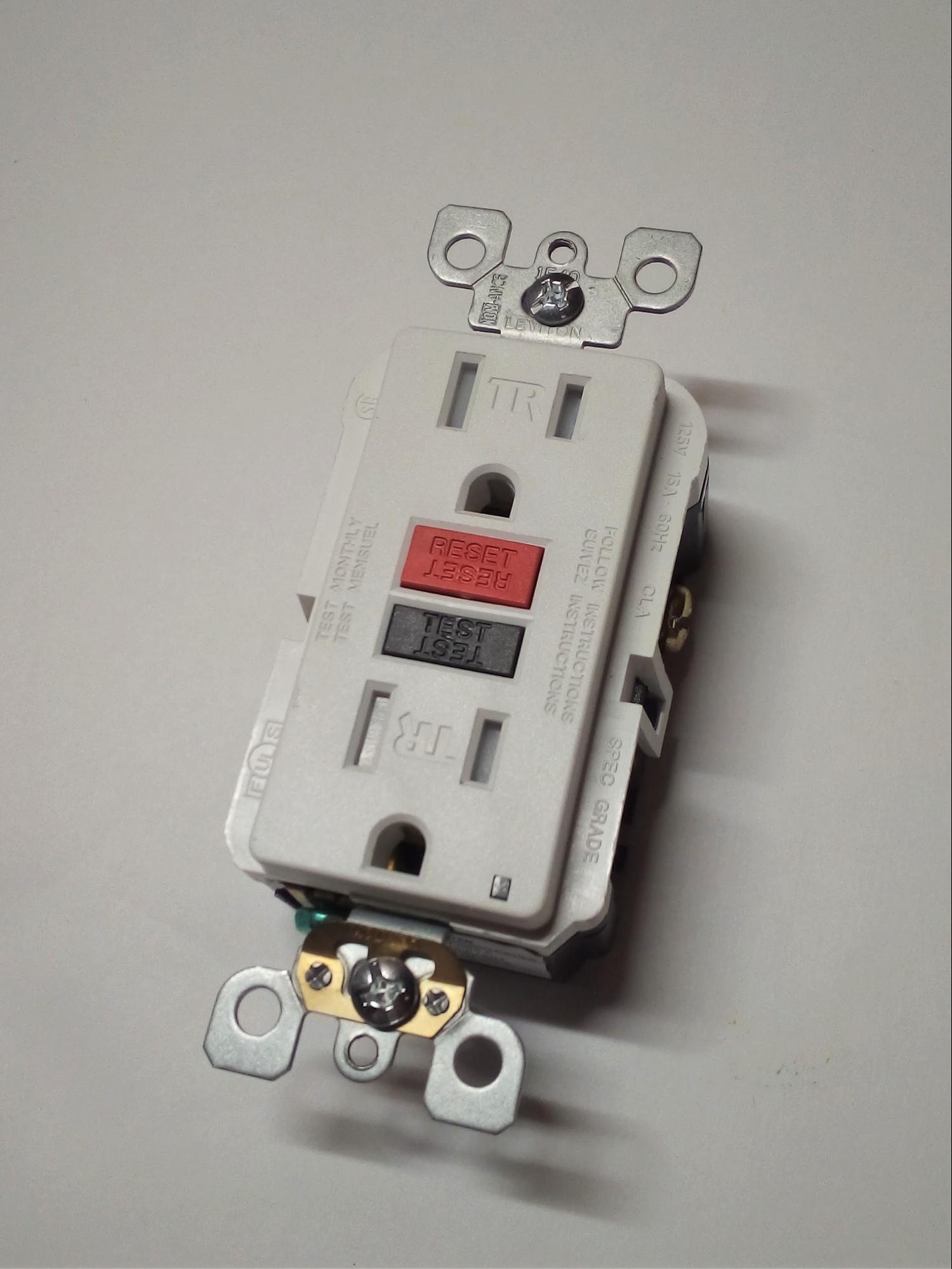
Figure 3. A GFCI-type outlet. Some breakers have integrated ground fault interrupters rather than including them at the individual outlets.
Machine Frame and Motor Grounding
Industrial machine frames and motors have very specific ground connection points, as well as requirements on the maximum amount of resistance that should be measured through the ground wires. They will ALWAYS measure less resistance than the load device they are protecting. Any failure (or, again, moisture) should travel through a ground path back to the source, ultimately tripping a breaker or burning a fuse.
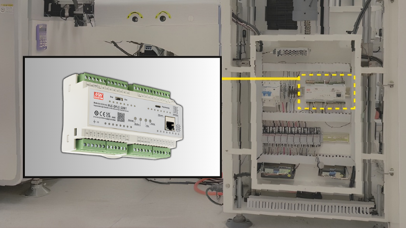
DC System Grounding
In DC voltage systems, particularly control systems, a ground network can prevent electromagnetic interference (EMI), or ‘noise’, from being introduced to communication wires by providing a protective layer around a wire.
EMI is introduced from motors and other AC sources, but it can be blocked by a grounded wire wrapped around the conductors in the cable. These ‘shielded’ wires have a woven or foil mesh just under the insulation jacket, which is attached to the ground network.

Figure 4. The ground connection of a PCB.
In this case, as a power supply board, it provides protection against noise and a redundant safety connection for the transformer on the board.
Control Cabinets and AC Power Distribution Devices
Ground connections inside control cabinets and around AC power distribution devices follow many of the same rules as the motors mentioned before. This type of grounding is also called ‘bonding’ and can be seen within every metal control cabinet. A green or green/yellow wire is attached to the cabinet with screws, locknuts, or special terminal blocks that attach the wires to the metal enclosures.
Transformer output wires will also be connected to ground using strategies that allow single or multiple voltage outputs while still maintaining the consistent path through one of those wires back to the earth-grounded network.
Electrical Grounding Fundamentals
Grounding is a common practice throughout nearly every electrical field. But for every specialty, the definitions and practices will be different.
A broad study reveals two basic grounding categories: equipment and personnel safety and signal protection and conditioning.
*Article originally published April 20, 2020, revisions have since been made.
Want to learn more about grounding and power in control systems?
-
Understanding Differences Between Power and Ground Side Switching
-
The Difference Between Ground and Neutral Conductors in Control Wiring
Related Content