Facebook
 Google
 GitHub
 Linkedin
Negative Effects of Grounding (Earthing) a DC Power Supply
DC voltage systems exist to provide controllers and field devices with stable power, but it is not always clear when these systems should be bonded with the earth ground of the AC line voltage supply.
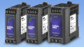
Industrial DC power supplies are common in control cabinets, most often used for powering field devices including relays, contactors, sensors, and in many cases, the controllers and I/O terminals. Perhaps the most common of these DC supplies are the DIN-rail mounted 24 V models, available with power output ranges from just a few watts to several hundred watts.
In these systems, there are two connection configurations: floating and grounded.
Although grounding a DC supply can often be a preferred method, it can introduce other problems including ground loop interference among sensors and a possible problematic current leakage to ground.
Floating DC Voltage System
A floating DC control system means that the DC power supply is energized with line voltage (including the bare earth ground), and the output includes only a DC positive (+) and a DC negative (-). These are usually printed as, respectively, the 24 V and the 0 V output terminals, ready for distribution to the control system.
Since this floating system maintains 24 V between wires, it will sufficiently power any device that requires such voltage and does not need any further connections.
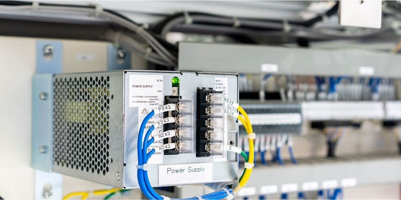
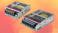
Figure 1. DC power supplies use an AC input (can be 1-phase or 3-phase) and provide a positive (+) and negative (-) output. Image used courtesy of Canva
Grounded (Earthed) DC Voltage
The competing model of grounded DC control systems include a connection from the DC (-) terminal to the earth ground of the building’s AC supply.
Previous articles have discussed some of the positive effects of grounding a DC system, but there are some concerns that may prevent an engineer from wanting to connect all parts of a control system to ground.
It is imperative to, above all else, be sure of the regulations. According to the UL 508A, there are certain conditions when a power supply must be grounded, including if the input to the supply is 3-phase or 1-phase 240 volt, or if that input is ungrounded. There are many more requirements for grounding in control panels, found here.
Ground Loop Interference
It will be observed in any properly installed system that green screw terminals will bond all equipment (PLCs, VFDs, etc.) to a nearby metallic body. This serves to provide a path to ground in the event of any active line voltage coming loose and touching a metal equipment case. With the path to ground, the short will cause a breaker to instantly trip or a fuse to blow, protecting users and the equipment.
If the DC (-) supply is also connected to ground near the power supply, there are now two connections to ground in any powered equipment. With two connection points, a full circle is created, called a ‘ground loop’. If inductive interference places a voltage on any metal equipment (even a conveyor belt frame), there is now a low-resistance path and current will travel. This can result in interference or harm to equipment, since that ground loop may not be in the path of a breaker or fuse.
Analog Voltage
Interference can be handled in different ways for various analog control signals. Differential pair signals use two dedicated wires, usually twisted together in a pair, to communicate with an analog sensor. Any interference on one line will also appear on the other line. Since the actual signal is the difference between the pair of wires, two sudden jumps in voltage would appear to be no jump at all.

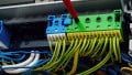
Figure 2. Differential pair wire sets serve to reduce interference in critical analog sensor systems. Image used courtesy of Canva
However, in many analog voltage scenarios, each 0-10 V signal is measured at an input terminal, and a single common wire provides a reference for all analog input channels. If this one common reference line experiences voltage fluctuations, all analog readings will be skewed. If the power supply providing this reference is bonded to earth ground, any ground loop interference will certainly cause errors in readings.
For this reason, if using analog voltage devices with common reference wires, it is recommended to keep the DC power supply floating and isolated from ground loops.
However, there are no absolute rules on when grounding a supply is the correct action to take. Even a floating DC system may experience interference, and in fact, a single ground connection may allow the interference to be harmlessly passed to the earth ground.
Measurement of isolated systems may help to pinpoint the location of the interference. If it is introduced into the DC control system, it may be beneficial to bond the DC (-) supply to ground to minimize interference effects. If the interference is rather introduced into the equipment nearby, it may not be useful to connect the DC system to ground.
Current Leakage to Ground
A final reason why earth connections may not be desirable in a DC supply might be evident in a system containing many DC power supplies. Inside many switching power supplies is an EMI-filtering capacitor used to remove irregularities introduced by the input line voltage. This capacitor spans from the input to the output stage of a switching power supply, and its effect can be measured as a small irregular voltage riding on top of the DC voltage.

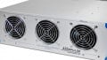
Figure 3. Current leakage from power supplies to earth ground can result in unwanted breaker tripping, if too many power supplies are used together. Image used courtesy of Canva
In one power supply, this will only result in a tiny amount of current, as the leakage through a capacitor is very small (less than a milliamp). If multiple power supplies are connected in a system in parallel, there may be a sizable current. If this current comes from the output into a grounded DC system, it will return through the ground wire, causing a trip of a ground-fault breaker.
Summary
It is nearly impossible in any discussion of grounding voltage supplies to provide a definitive recommendation on whether it is best practice or not. However, understanding positive and negative effects can help an engineer to evaluate a unique system and determine if grounding may solve recurring problems.
Want to learn more about grounding and power in control systems? We have plenty more!
- Fundamentals of Grounding in Automation Control Systems
- The Importance of Grounding Equipment for Safety
- Understanding Differences Between Power and Ground Side Switching
- Grounding for Control Transformers
- Grounding DC Power Supplies
- The Difference Between Ground and Neutral Conductors in Control Wiring
- The Importance of Neutral Wire in 3-Phase Systems
Related Content