 Facebook
 Google
 GitHub
 Linkedin
Understanding Voltage Drops of Capacitors and Inductors
In circuit theory, voltage drops of resistive type devices are relatively simple because they do not change over time. But there are two types of devices that do create changes over time: capacitors and inductors.
Discussing voltage drops of resistive type devices (including wires) is relatively simple because they do not change over time. As soon as voltage is applied to the circuit, the current begins flowing, and power is dissipated in the devices, leading to steady voltage drops. But there are two types of devices that do create changes over time: capacitors and inductors. This article discusses how to account for voltage drops in these special cases.
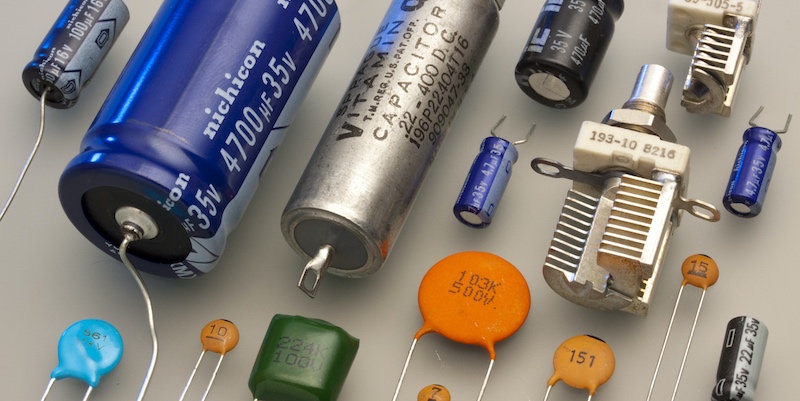
Figure 1. A selection of different capacitors. Image by Eric Schrader. [CC BY-SA 2.0]
Three main categories of load devices exist in electronics. Typically, purely resistive loads are the first to be introduced in an electronics course or program due to their simplicity. As long as voltage is applied to a properly constructed resistive circuit, the current immediately flows through the circuit at a steady rate. This leads to the conversion of energy in each component, and therefore a voltage drop.
The key characteristic of resistive loads is that they do not change, no matter how long the circuit is active. In reality, small changes are inevitable — even current in a device changes its temperature, affecting the resistance. So there is no way for a real circuit to remain exactly the same. But in a resistive load, the current can be assumed to remain largely the same regardless of elapsed time.
The other two categories of load devices can be more difficult to discuss. The effect of each one on the circuit changes depending on the voltage type, i.e., DC or AC application. These components are the capacitor and the inductor.
One further important note to keep in mind with these devices is that they never act alone in a circuit. Some circuits may be purely resistive, but there will never be a purely capacitive or inductive load. They both include some element of resistance even if that resistance value is wrapped up within the capacitor or inductor itself.
Capacitor Voltage Drops
As discussed in previous articles, a voltage drop is defined as the difference in potential energy divided by the charge which would move through those points. As long as we can determine how the energy is changing as current travels through a load device, we can then determine the voltage drop — or at least, we can determine how the voltage changes over time.
A capacitor is any component with two conductors separated by an insulator. Sometimes this is an undesirable effect, such as two wires side-by-side in a wire bundle. Other times, the device might be constructed carefully with conductive plates and dielectrics in order to maximize the amount of capacitance.
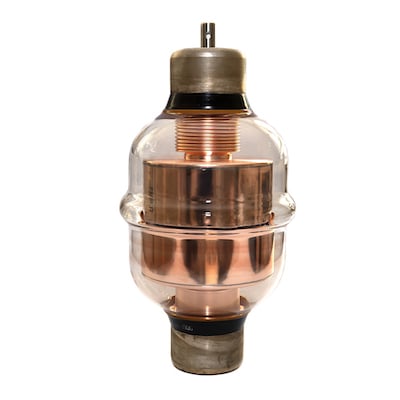
Figure 2. High-voltage vacuum capacitor.
As soon as voltage is applied to the circuit containing the capacitor, the charge begins building on one of the conductors since it can’t travel through the insulative layer. At the same moment, the opposite charge begins building on the opposing conductor. Another way to think about this is that while a negative charge begins building on one side, a positive charge builds opposite, causing the negative charge to keep traveling through the circuit as if the capacitor wasn’t even there.
From this initial description right when voltage is applied, we can conclude that the charge motion ‘through’ the capacitor is extremely high, and it does not take a lot of energy to attract the charge on the opposite side. If the required energy for motion is low, and the charge motion is high, the voltage is low:
Over time, perhaps just a few milliseconds, the opposing charges will continue building on both conductors. As that difference increases, so does the energy required to keep building the charge. As the rate of charge growth slows down, the motion of the charge in the circuit will also slow down. This leads to a high voltage:
Perhaps the exact values of the components in the circuit can help to calculate voltages and currents, but at least from these observations, we can give an initial assessment. When voltage is first applied a discharged capacitor, the current will be high and the voltage drop across the capacitor is low. Over time, the current will decrease and the voltage will increase until we reach the maximum (source) voltage, at which point the current will cease entirely.
Inductor Voltage Drops
Inductors are usually discussed right alongside capacitors (just like right here in this article) but be careful - the principle of operation is ENTIRELY different. The only similarity is that inductors do exhibit changing voltage and currents over time, although in a different manner than capacitors.
An inductor is a coil of wire, usually wrapped around a core of metal consisting of iron composites. That iron is capable of holding energy in the form of a magnetic field, although it’s not permanent.
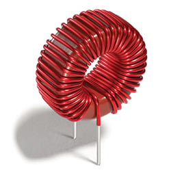
Figure 3. Toroid inductor. Image courtesy of Coilcraft.
When voltage is first applied to this coil, the energy is largely transferred from the charge in the circuit into the magnetic field of the iron core. Thus it takes a lot of energy to build up that magnetic field. At the very beginning, it will take the most energy. Based on the formula for voltage, this energy difference in the coil will lead to a large voltage:
Over time, the energy stored in the magnetic field will reach a maximum, and it doesn’t take any more energy to keep building. When that happens, the voltage across the inductor will drop:
Changes in Current
One important difference between capacitors and inductors is the initial charge motion (current) and the changing amount over time. An inductor is a coil of long, thin wire resulting in a measurable resistance. The current in a pure capacitor at the beginning may be very, very large with a nearly zero resistance. We would expect the same extremely high current in an inductor after time when the voltage drop is low. However, the internal resistance of the coil limits the current.
For this reason, we will never see a load device consisting of just a capacitor. However, we might expect an inductor as a load, since it also has a considerable resistance of its own. In fact relays, contactors, solenoids, and even motors consist simply of coils and are inductive loads - but they still have an internal resistance to limit the current.


What are applications of capacitors?
Capacitors are used in many places.
1. Power Supply Filtering: Capacitors are used in power supplies to filter out any noise or ripples from the main incoming AC supply.
2. DC-DC Converter Output Filtering: Capacitors are used to filter out the high frequency switching noise generated in DC-DC converters.
3. Coupling: Capacitors are used to couple two circuits together, allowing AC signals to pass while blocking DC signals.
4. DC Blocking: Capacitors are used in circuits to block any DC signals from passing, while allowing AC signals to pass.
5. Timing: Capacitors are used in timing circuits to control the rate at which current flows.
6. Audio Equipment: Capacitors are used in audio equipment to filter out unwanted noise and smooth out the signal.
7. Motor Start and Run Capacitors: Capacitors are used in electric motors to help start them up and then keep them running smoothly.
For more electronic components products, please go to QUARKTWIN official website.