Facebook
 Google
 GitHub
 Linkedin
Panel Builder’s Guide to Grounding and UL 508A Standards - Part 1
Ground wires reduce the risk of injury and damage from faulty equipment. Shops designing according to the UL 508A standard must understand how, when, and why to properly ground and bond circuits.
Equipment grounding: everybody’s favorite topic.
Actually, I find the subject of ground wires quite interesting, not just from the aspect of increased safety, but also because it helps me better understand some of the more complex systems, like high-leg 3-phase supplies and unusual configurations of transformer secondary coils.
Grounding and Bonding Control Panels
Understanding the general idea of grounding is definitely a good starting point before trying to understand the regulations as to proper use and installation. But once you have the basic fundamentals, the next step is to understand what the UL 508A and NEC have to say about grounding/grounded circuits.
Control Panels: UL 508A Section 14 - General
The first introduction to grounding for control panels explains a few of the general conditions for requirements on grounding. First, panels must have a way to ground all metal components that could be contacted by a person (pretty much all of them). Any loose wire or faulty connection could cause an energized conductor to touch the box, and it must be able to trip the breaker under such circumstances (14.1).

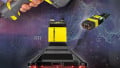
Figure 1. Normal grounding methods showing with colored insulation, tape, grounding screws, and grounding terminal blocks, all showcasing the typical green or green/yellow coloring.
A conductive ground terminal on the panel must provide a secure connection to equipment and to all the metal parts inside (14.2, 3).
Finally, for those boxes that include a line cord, like a training panel or roll-around equipment, you must use a line cord with a grounded plug (14.4).
So far, pretty straightforward.
Control Panels: UL 508A Section 15 - Sizing
Drilling down into the specifics, the next section discusses the size of the conductors used to ground the equipment.
The reason this is so important is the resistance of the wire. If an energized line comes loose and touches metal, there is virtually no load resistance. If a ground wire is used to return that energy back to the main panel or to ground, there must also be sufficiently low resistance so that there will be no voltage drop and the current will be high enough to trip the breaker.
Think about it this way. Say you have a supply breaker of 300 amps in a panel running on 208 volts. If an energized wire comes loose from a terminal block and touches the wall, you better hope the current will immediately exceed 300 amps and trip the breaker. If your ground wire was 8 AWG, it has a rated resistance of roughly 0.64 ohms per thousand feet. Most likely, your ground wire length actually is below that value, but using this number, the total current in the ground circuit is only 325 amps, barely enough to trip the breaker.
Based on this knowledge, you can see how important it can be to properly size the conductors.
The table published by UL 15.1 in the UL 508A standard provides the proper sizes for both copper and aluminum wires.
One special note considers the ground wire between the main cabinet and the hinged door. If there is a special breaker or fuse for the HMI or other equipment mounted to the door, use that ampere rating to size the door grounding strap, not the overprotection current for the main panel breaker (15.2).
Control Panels: UL 508A Section 16 - Transformers
Transformers and power supplies, since they convert voltage and current from one level to another, exist in a category of their own. Most primary coils (the input side) will be grounded at or near the main supply, but the secondary (output) may also be grounded depending on the specs of the transformer. Following are some further details on transformer ground requirements.
Two levels of secondary voltage output define which rules to follow. Above or below 50 volts at the output is the defining threshold. (16.1)
Below 50 Volts
The output must be grounded if the supply voltage is ungrounded OR if the supply is above 150 volts. So if you are using a 120-to-24 volt step-down transformer for some 24 vAC valves, the secondary does not need to be grounded, as long as the primary IS grounded.
Above 50 Volts
The output must be grounded so that the maximum voltage of any conductor with respect to ground would be 150 volts. In a normal electrical panel, the line-to-line voltage is 240 volts, but the voltage of either line with respect to the grounded neutral center-tap is only 120 volts.

Figure 2. A typical 1-phase transformer grounding configuration, conpared against a more unusual configuration with a conductor that exceeds 150 volts with respect to ground.
Based on this information, it would fall outside of UL specifications to leave such a configuration (left side of the above image) ungrounded, or to ground one of the line conductors such that the center-tap-to-ground is 120 volts, and the voltage of the second line-conductor-to-ground is 240 volts (exceeds the 150 volt maximum) but indeed, this would be an unusual grounding configuration (right side of the above image).
3-phase Configurations
Several 3-phase transformer configurations are grounded. 4-wire wye and delta are grounded, with the center (neutral) of the wye being grounded, or the center leg neutral of the delta being grounded.
Monitoring a Fault Detection
Finally, when a system output is more than 100 volts and does not fit any of the above grounding requirements, it must still be outfitted with monitoring or interrupting devices to detect and correct any ground faults. (16.4)
Control Panels: UL 508A Section 17 - Identification
There are two distinctions in the section: grounding circuit conductors, which are the actual grounding/bonding wires, and grounded conductors, which are the wires that are bonded to ground, but are the connection point for field wiring devices (such as a grounded neutral).
Grounding Conductors
The color green, or a selection of text indicating ‘Ground’ or ‘Gnd’, denotes the requirements for grounding conductors. The wire must be uniquely insulated by green or green/yellow insulation, or if the insulation happens to be any other color, it must have green tape at the ends. All grounding screws and connection points must also be green colors and/or have clear labels with the selection of appropriate text. (17.1-3)

Figure 3. Although not all of the screws meet the UL 508A standard (green and hexagonal), the inclusion of the grounding symbol satisfies the requirements for grounding conductor terminals.
Grounded Conductors
The secondary side of a transformer will have one conductor bonded to ground, as discussed previously. This conductor, while still used in the circuit as a current-carrying wire, must be clearly marked.
This conductor will be insulated white or gray. If the insulator has a different color, such as from built-in wire harnesses that you cannot control, the end connection points must be marked with white tape. (17.4)
Grounding for Control Panels
Although this article serves as a basic explanation of many of the grounding requirements from the UL 508A specification, it does not contain all of the grounding requirements, and care should always be taken to consult all relevant documents for any assembly or repair process.
Hopefully, this article serves to translate and summarize a few of the requirements in a more reader-friendly format for those trying to brush up on this often-confusing topic.