Facebook
 Google
 GitHub
 Linkedin
Grounding for Signal Conditioning
Grounding electrical systems can lead to problems with interference and noise, affecting signal clarity. This article looks at these problems and how to avoid them.
The concept of grounding and its related terms are not just present when we are connecting machine centers and outlets in order to minimize safety risks. Grounding principles can be a benefit (and sometimes a problem) when dealing with low-voltage signal communication as well. Understanding a few of the terms related to the field of signal conditioning can help with the design of effective grounding systems.
For anyone experienced in the field of industrial electrical work, the idea of interconnecting metallic components on machines and devices is not unusual. Quite the opposite — it’s a routine and often mandatory task to provide appropriate ground conductors between machines to minimize shock hazards and ensure circuit protection devices can accomplish their jobs in case of failure.
Since nearly all modern machine centers and operations include at least some element of a digital control system, the effects of very low-voltage and high-frequency signal injections into communication lines also come into consideration. Those considerations aren’t as necessary when dealing with large output devices like motors and solenoids since it takes a substantial voltage for a relatively long time duration before an adverse effect is felt. But digital communication lines (such as RS-232, USB, Ethernet, etc.) and I/O channels which use very little power can both be adversely affected by interferences.
Equipment grounding can solve some of the problems created by interference and noise, but it can also add new problems. This article looks at three main topics when dealing with grounding that can affect signal clarity: ground loops, shielded cables, and the importance of proper placement of I/O wiring.
Electrical Ground Loop
Normally in a facility, each machine or cabinet is connected to ground by a solid screw lug or terminal. This allows each metallic surface to be grounded back to a single connection point.
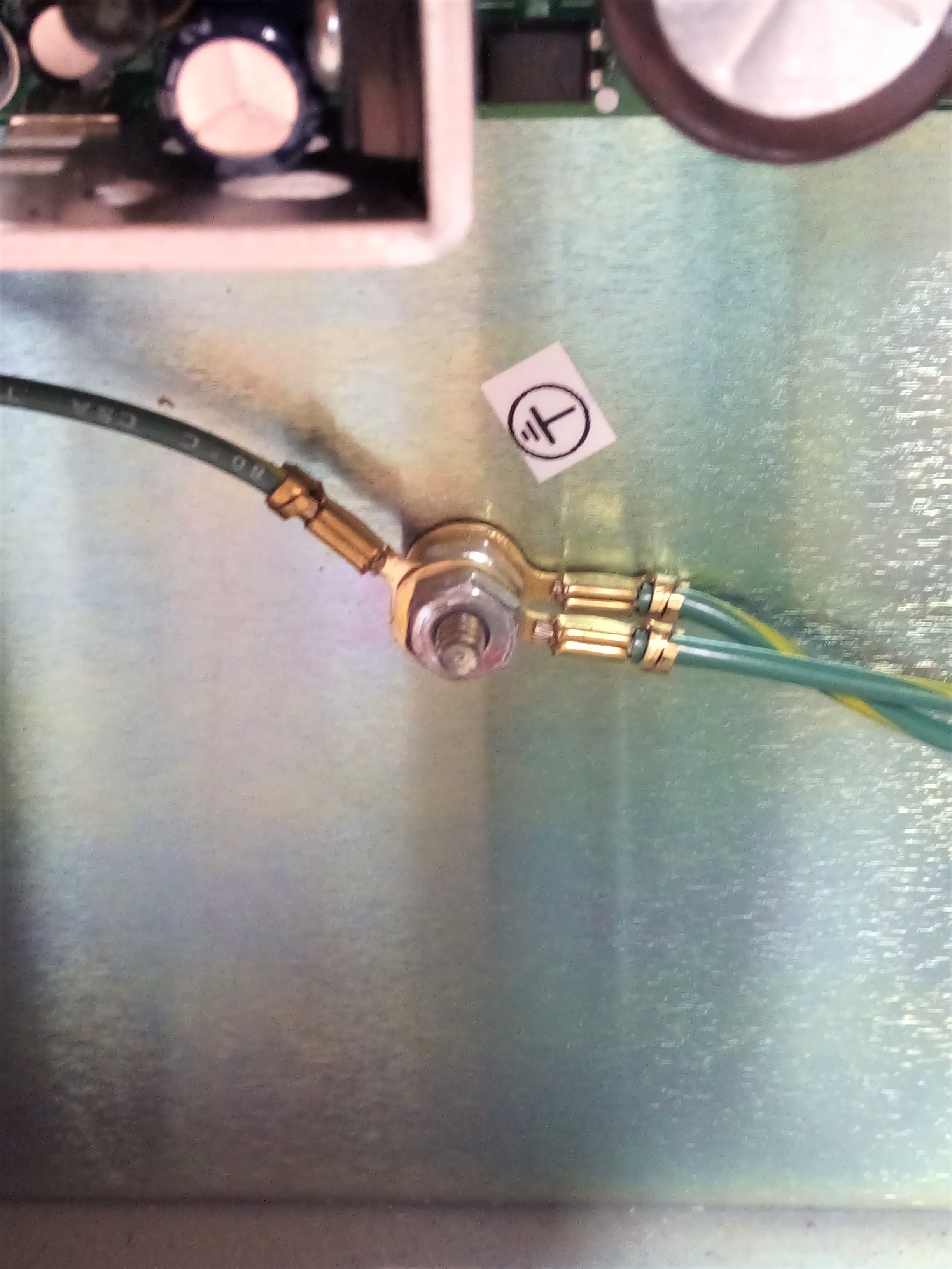
Figure 1. This is referred to as a ‘star’ configuration. Image used courtesy of the author
Now imagine in this facility that another ground wire is spanned between one of the grounded machine frames and one of the grounded control system boards. Since they were both grounded already, this redundancy does not seem like a breach of protocol. However, the previous star configuration now begins to look like a spiderweb, forming separate loops throughout the ground network.
A ground loop can be harmful to signal quality because of the way alternating signals travel in a loop. It’s essentially a single-turn transformer capable of inducing voltage on any signal wires nearby. If any section of that ground loop is exposed to interference, it will travel in a loop through the complete circuit with very low resistance, and therefore a relatively high current. This was not an issue when each machine was terminated with a single dead-ending ground wire, only used when an electrical fault completed the circuit.
The issues usually appear here when a new cable is introduced which suddenly causes faulty or unstable signals when none existed before. This usually happens with shielded cables or I/O devices with devoted grounding wires that span between both devices.
As a general rule, if each machine is grounded already, DO NOT connect extra ground wires for redundancy, especially if they run along the cable routes alongside signal wires. If the grounds already exist and are verified, leave them alone and do not add more. However, if a cable is shielded, other considerations need to be made.
Shielded Cables
Physically, these grounded or shielded cables have a wire mesh or foil wrapping around the wire bundle, just under the insulative jacket. It’s not a single wire passing through along with the others.
Rather, it forms a barrier around the bundle, absorbing and dissipating any electromagnetic interference much like the metal frame of a building absorbing RF signals and blocking cell reception. This is called a Faraday Cage, and a shielded cable is nothing more than a small cage around a set of wires.
If both ends of this shielded wire are connected to pre-grounded equipment, it can cause additional harm by forming the ground loop described above. Sometimes, the recommendation is to connect only one end of the shield conductor, so that it can still absorb interference and pass the signals back to the common ground, but will not create a conductive loop.
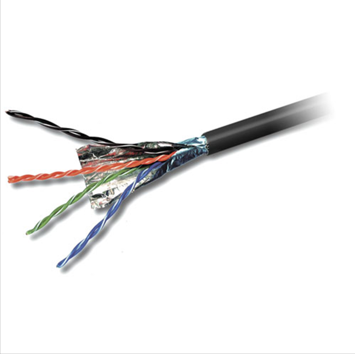
Figure 2. Belkin CAT5e Stranded Bulk shielded cable. Image used courtesy of Belkin.
However, it is important to note two distinct cases considering shielded cables. If a manufacturer’s specification calls for a shielded cable in an application, it has almost certainly been designed with filter circuits that inhibit ground loop current. The shield conductor has already been attached to the internal chassis ground, and the shielded cable can be installed without concern.
However, when replacing a standard cable (like a serial, USB, or servo drive cable) and using a shielded cable in its place to reduce interference, those filters are not likely to be in place. In these cases, it is recommended to connect only one end of that shielded cable to ground, assuming the devices on each end are already solidly grounded.
I/O Wiring Placement
In the event that a ground conductor is carrying current (which it often is to some small degree), it can cause interference inductively to other cables nearby. This interference often isn’t enough to cause signal failure for discrete devices, which must rise from 0 to 24 volts to enable an input or output signal. However, it can be a huge impact on analog devices that rely on precise voltage and current levels to transmit values.
Two simple strategies exist to combat interference from ground. The first strategy is to remove the signal wires away from ground conductors when traveling between machines. But this is often easier said than done, since often the metallic machine itself is the conductive path, and wire bundles travel nearby, attached to the machines. But if possible, remove signals from ground.
The other strategy, if the wires must be right next to ground no matter what, is to use differential voltage signaling and to ensure that both the voltage and the reference signal are right next to each other.
The receiving module will only look at the difference between the voltage and reference (common) wires. If there has been some interference from the ground conduction, it will cause the same waveform on both wires, so the difference between them will still show the proper value.
Maintaining Signal Quality When Grounding
Grounding equipment is a necessary task, but often can create problems with signal quality. If a device fails to communicate reliably, or starts experiencing random values on a regular basis, first try to evaluate what is happening when those failures occur, or when they started occurring. This may point to the device at fault, and it may have to do with a grounding issue. They can’t all be avoided, but the effects can often be minimized with proper installation.