Facebook
 Google
 GitHub
 Linkedin
So, You Got a Modbus TCP Device… What Next?
Despite being one of the oldest protocols in automation, Modbus is still more complex than digital I/O. When you have a Modbus TCP device, what do you do? How do you actually use it?
I have a solid love/hate relationship with industrial protocols. On the one hand, I love to try out a new device, learn the details, and see it work successfully on a test bench setup. On the other hand, the path to success usually takes a few hours of browsing manuals and forums in frustrated desperation.
Modbus TCP is a very popular protocol, not only because of its legacy but also because of its simplicity when routed over a normal Ethernet interface. Still, when it comes to actually using a device, it’s nice to have a plan in mind.
This article will describe the implementation of a 5-segment stack light (Patlite LA6-LAN) that uses registers for instructions. I cannot promise that every device and PLC will act just like this, but the framework will apply to nearly any scenario.
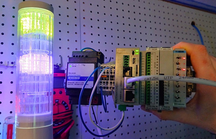
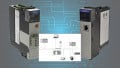
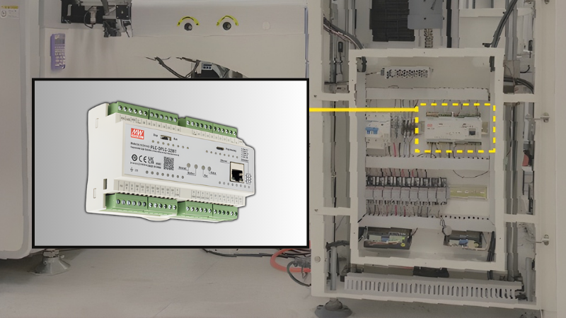
Figure 1. PLC with a Modbus stack light.
Difference Between Ethernet/IP and Modbus TCP Devices
The main differentiator of Modbus from most other protocols is simplified into one word: consistency. Most other transmission protocols can adjust to the type of data, with packets becoming longer or shorter depending on whether we’re downloading a video or sharing a few discrete I/O points. This means we need to inform the sender and receiver as to the number of bytes of incoming and outgoing data.
If you’ve ever set up an Ethernet device, you’ve experienced this. You need to select the assembly instance and number of bytes for input, output, and config data before trying to communicate with the device. Alternatively, you may find an electronic data sheet (EDS) file that automatically establishes those parameters. But not so with Modbus.
In the Modbus world, there are only two required variables: a function code that tells the receiver what type of data to expect, and the starting address for that request. If it’s output info, you’ll also need to tell it what value to place in those addresses. Because the Modbus device always knows what to expect, we don’t need to set up the new device with any EDS or Ethernet profile. Simply send the Modbus transmission.
Example Operation: Stack Light
In this project, we’ll illustrate with a Patlite LA6-LAN tower light. This RGB light has 5 levels, the color of which is selected via a web server. After that, a PLC can turn each level on and off with a Modbus transmission.
Setup
When the tower light is powered and connected to a PC via Ethernet cable, the web server can be accessed. The default IP address is 192.168.10.1, and on first setup, a password is created. You need to set the IP address to the same subnet as the Modbus PLC. In the Modbus menu, be sure that it’s enabled, and you can leave the default port at 502.
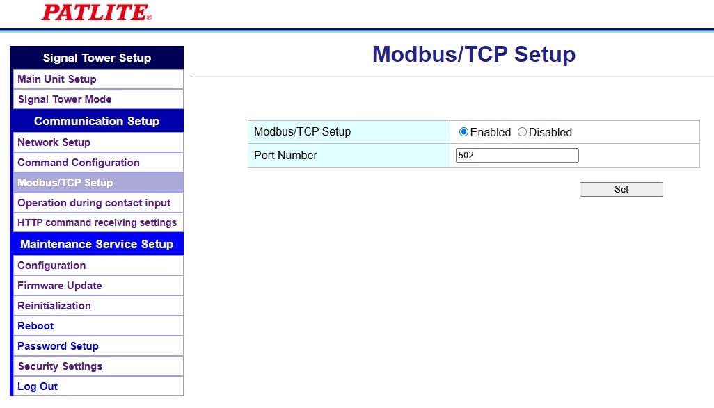
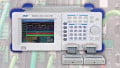
Figure 2. Verifying Modbus communication.
PLC Connection
As we established, the simplicity of Modbus means that we don’t need an EDS, even though this is a LAN device, and it feels like we need to create a new device in our project.
Nope, we’ll simply need to use a Modbus command with the proper IP address. The only physical connection is a LAN cable, and the verification that both the PLC and the device are on the same subnet.
Understanding the Function Codes
This is the single most confusing point for using Modbus devices. In this stack light, we examine the user manual to find the answer to two key questions.
What function codes can be used?
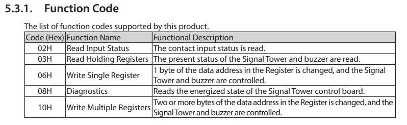
Figure 3. Valid function codes for this product.
From the table above, we can read both contacts and registers, but we can only write to registers. This means that, to turn lights on or off, we must use function codes 6 or 16.
If registers are used for outputs, what values should be placed into the registers?
If coils had been used for outputs, we would simply use boolean tags to write a 1 or a 0. But a register is a 16-bit integer, so we must have detailed information about which values will create a response. In this stack light, we can turn the lights on, off, or flashing, so we need more than just 1 and 0 coils.
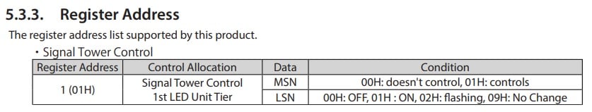
Figure 4. Command and control byte data.
According to the table above, we see that the first register address needs to be sent bytes to control the light, and to turn it on. To control the light, bytes 01, then to turn it ON is also 01. In binary, as a 16-bit integer, this is:
0000 0001 0000 0001
Converted to decimal, this equals 257.
Likewise, to turn the light off, send 01 00, which is 0000 0001 0000 0000, equaling 256.
If we want to flash the light, send 01 02, which is 0000 0001 0000 0010, equaling 258.
Sample Command
Now that we know what needs to be sent, let’s examine how to send the command with a couple of different PLCs.
First, most AutomationDirect PLCs use a similar format: a MWX (Modbus Write) command. In the Productivity Suite environment, we need to define tags that will hold the values for the registers. In this example, I used some toggle switches that populate integer tags with either a 257 or a 256.
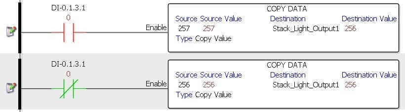
Figure 5. Adding data to the tags.
Once the tags are populated, the MWX command directly writes the message to the Modbus device.
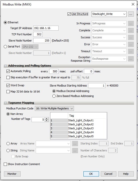
Figure 6. Modbus write parameters.
The Modbus device IP is added, while port and node numbers stay at default values.
Automatic polling is added so that the rung of logic doesn’t need an input. 500 ms is a sufficiently high frequency for this task.
The starting address is 1 for the top stacklight level, in accordance with the documentation.
To use the tags, the function code is 16 (multiple registers to control all tiers at once). The tags come from the toggle switches in the previous lines.
Once this code is downloaded, the lights respond exactly as expected!
For a Rockwell Studio 5000 code, we can use the readily available AOI from the download center. Extract the folder and ‘import rungs’ to use the Modbus TCP client instruction. When created, the name of the tag will be Client_01 by default, but you can Find/Replace all tag instances to ‘StackLight,’ or to a better name.
Everything required for the Modbus transmission is contained in the tags.
First, the data to be sent to the Modbus registers should be populated. For simplicity, we’ll use the same strategy as the previous example. Press a button to light up the tier, release the button to turn it off. The MOV command sends a 257 or 256 into the appropriate Data.HoldRegisters tag.
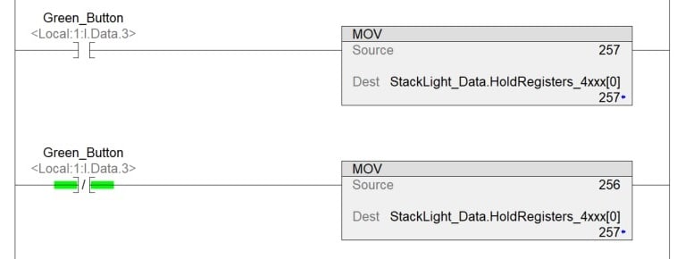
Figure 7. MOV commands to add data to the tags.
Next, we need to set the destination IP address for the device. This PLC has a single embedded Ethernet port, so it does not need a local address.
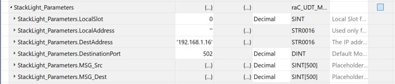
Figure 8. Tags to set up the communication.
Finally, set up the transaction (message) details. I set the poll interval to 500 ms. The transaction type is 16, meaning ‘write multiple coils.’ The beginning address is 1, and there are 5 integers to be sent. Remember, those integers were defined in the Data.HoldRegisters tags.
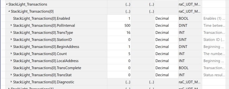
Figure 9. Tags to set up the message details.
When we set this Transaction.Enabled tag to 1 and are successfully online, the stack light should reflect the values as assigned in the HoldRegisters tags!
Consistent, but Not Simple
Judging from the previous descriptions, the strength of Modbus is not, perhaps, in simplicity. However, for most protocols, we must add a new device to the project, then figure out how to send messages. Modbus removes the first step, so it does offer some simplicity.
The nice thing about practicing with Modbus is that you can find such devices everywhere, so it helps in learning some of the details and getting hands-on with a new control method.