 Facebook
 Google
 GitHub
 Linkedin
What’s This Standardized Code for Information? Funny You Should ASCII
ASCII is a familiar acronym, found in applications like Modbus communications and string data types—but what is it, and what does ASCII mean for automation engineers?
Not every signal that travels down the wire of a control system is a binary high/low voltage pattern. But most of them are.
Discrete patterns are the signature of digital control systems from the NO/NC contact blocks of push buttons all the way to Ethernet packets of data hundreds of bytes long. But somewhere in between must lie the earliest forms of digital codes and patterns used to transport data between devices in a structured, universal method that could be understood by any kind of machine.
One of these digital codes used in early machines, and still existing today, is known as ASCII, and although many have heard of this code, it is only understood by those who have found a need to ‘look under the hood’ and discover how it works.

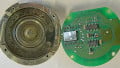
Figure 1. Binary signal patterns are detected with logic analyzer tools.
What Is the American Standard Code for Information Interchange (ASCII)?
The American Standard Code for Information Interchange is the definition of ASCII. Certainly, by those terms, it’s clear that this was designed to be a standardized format and obviously meant to transmit information between machines.
What kind of information? Nearly any kind whatsoever.
Do you need to send number values between machines? ASCII can do it. Need a string of text or a full sentence? ASCII. Punctuation and computer code syntax characters? ASCII. Need to tell a printer to make a space or a new line? ASCII.
With that much information, there needed to be a standardized way to list what binary pattern should relate to each character, number, and letter.
What Is the ASCII Table?
The chart known as the ASCII table is a handy reference when a single character must be known. Depending on the circumstance, each ASCII symbol can be represented in binary, as it would appear to a computer, or as the decimal equivalent, for easy human assignment, or hexadecimal, as a computer program might use for brevity.
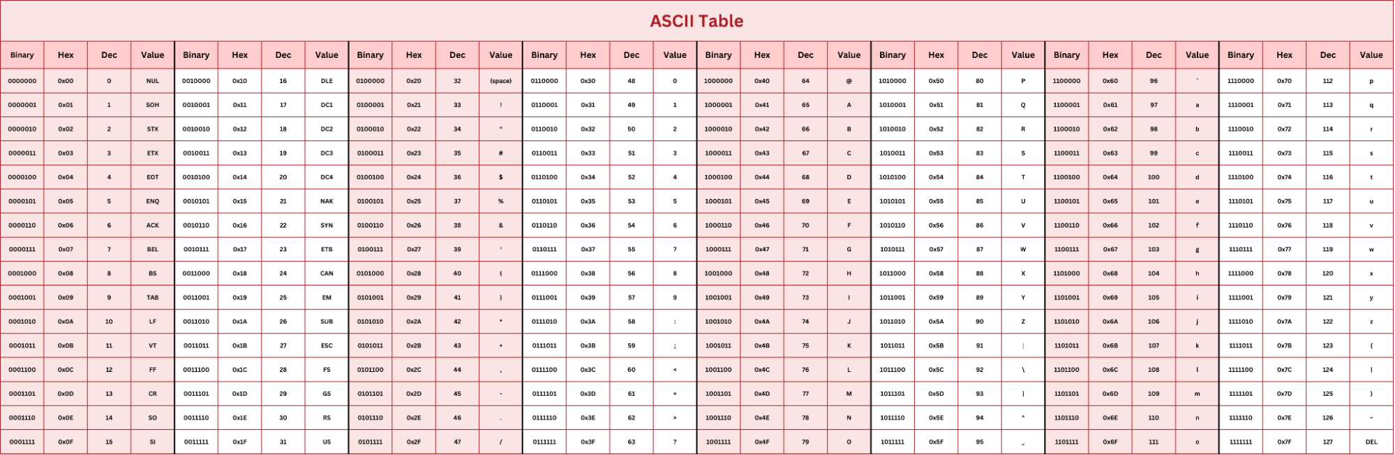
Figure 2. ASCII Table (Click to Enlarge).
Each ASCII value or symbol is represented with 7 bits. The reason this is 7, and not 8 as a typical byte, will be explained in a moment.
Since there are 7 bits, the total number of characters on the ASCII table is 127 in order to include all numbers: both upper and lowercase letters and all sorts of punctuation symbols that you will recognize on a typical keyboard.
Why Does ASCII Have 7 Bits?
The reason for this is a necessity. The total number of characters needed does not (at least originally) exceed 128. Perhaps if it had been made in modern times, we might have devised extra characters for emojis, but I digress…
The problem, however, is that data is transmitted in packets of 8 bits, the ‘byte’. What do we do with the extra bit?
Parity Bits and Error Checking
With 7 bits being transmitted at high speed, there is a chance that external signal noise, or simply reading accuracy, will somehow miss one bit every once in a while. To preserve accuracy, a single bit can be added to a signal in order to make the total number of 1’s in the signal either odd or even. This is called ‘odd parity’ or ‘even parity’.

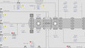
Figure 3. A computer’s COM port settings, in typical serial format, show both the parity selection type and the type of signal for indicating a message end.
For example, if we transmit an uppercase ‘T’ in ASCII, this is binary code 1010100. If we designed the system for ‘even parity’, the transmitter would read 3x 1’s in the pattern and add one more to make a total of 4x 1’s.
If the receiving controller reads an odd number of 1s, it can return a reply that the signal was corrupted and should be re-sent. The chances of two bits switching in a single transmission are even rarer but possible, so more advanced error checking (CRC, LRC, etc., a topic for another time) is available.
How Does Modbus ASCII Work?
Sending data by Modbus involves knowing a function code and an address. If the address (either a coil or a register) is meant to be written, the Modbus message will also include the value to be written. Inside a Modbus, the message is a few critical pieces of data to indicate when a message is starting, who it is meant for, the actual data itself, and the end of the message.
In the Modbus ASCII method, the beginning and end of the messages are marked with ASCII characters, allowing the timing between messages to be variable. This was helpful when computers transmitted at relatively low speeds with fairly low data loss.

Figure 4. Over the years, serial data transmissions have employed all sorts of cables, connectors, and terminators, like the DB-9 and DB-25 shown above.
These days, with high-speed communication terminals, messages can be started with precise delays or single bits, allowing for much more efficiency in the Modbus RTU format. Additionally, error checking is more comprehensive in Modbus RTU.
Most RS-232 and RS-485 devices are selectable between either Modbus ASCII or RTU. The engineer usually does not need to understand the fine details as long as ALL devices on that network are of the same pattern since ASCII and RTU are incompatible with this differing message format.
What Is ASCII Used For?
As an engineer, you may never never need to learn behind the scenes of ASCII codes. However, if you work with characters or strings, it may be quite important to at least understand the basic concept. When text strings are sent, they can begin and terminate with various characters such as ‘null’ or ‘new line’ or others. With at least a basic understanding of how standardized codes can interpret everyday information, it can be much easier to diagnose errors in communication.


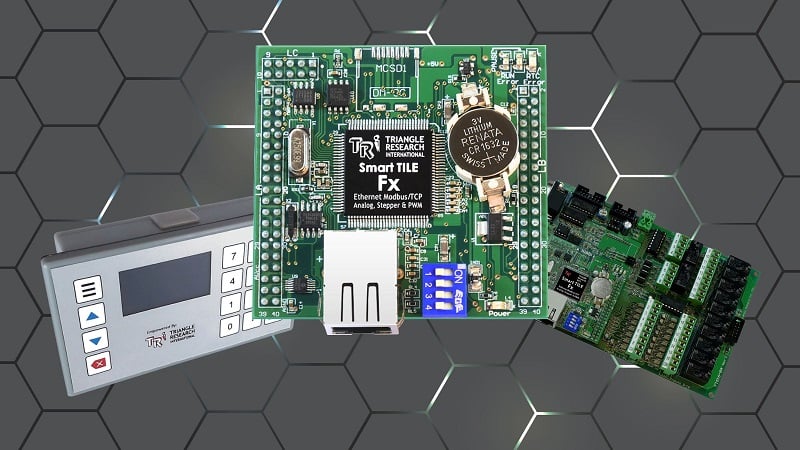

Correction: The IEEE-488 connector on the right in Figure 4 was developed specifically for parallel communications (GPIB), not serial communications. The DB-25 connector was widely used in telephony era of internet communications with Bell 202 modems.