Facebook
 Google
 GitHub
 Linkedin
Modbus: The Original Industrial Fieldbus Protocol
This article introduces Modbus, an industrial protocol that laid the foundation for fieldbus communication in industrial systems.
A fieldbus is a communication protocol used in industrial networks to connect field devices to industrial controllers. A fieldbus reduces the amount of wiring needed between controllers and devices because multiple devices can connect to the same pair of wires.
There are a number of popular fieldbus technologies out there, including Modbus, Profibus, Foundation Fieldbus, ControlNet, DeviceNet, and many others.
In 1979, Modicon introduced a new protocol leveraging the application layer of the OSI model specifically for use with its PLCs. This protocol was called Modbus and became the first widely used fieldbus in the history of automation.
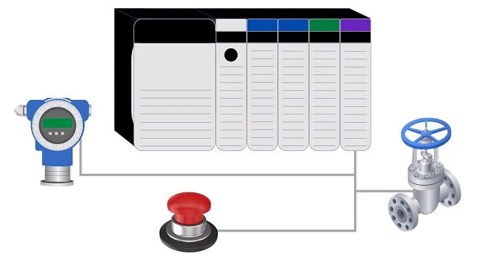
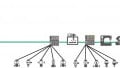
Figure 1. A PLC connected to field devices
Introduction to Modbus
Modbus was designed to connect field devices to industrial controllers. At the time of its invention, most devices used voltage or current representations as a means to communicate the device's state. Modbus can effectively handle discrete bits that reflect high/low sensor and actuator states, as well as registers that hold integer values that equate to analog process values.
The slow transition to fieldbus technologies resulted in Modbus being one of the simplest protocols and new versions have been added over the years.
Originally, Modbus was implemented over a serial communication link, i.e., RS-232/RS-485. These variations are still commonly used under the names Modbus RTU and ASCII. Eventually, the protocol was adapted for use over TCP/IP and Ethernet. This is commonly referred to as Modbus TCP, and is the most common implementation of Modbus for modern installations.
Communication Model
Modbus uses a master/slave model for communication (client/server in Modbus TCP). A Modbus master sends a request to a Modbus slave which performs actions and responds to the master. In this scenario, a master is often a PLC, with field devices behaving as the slaves.
A message frame in Modbus is composed of an application data unit (ADU) and a protocol data unit (PDU). The ADU differs depending on the type of Modbus being used, while the PDU is independent of the communication method.
A PDU is normally composed of a function code and some data. This is encapsulated in the ADU by an address and error checking code. Modbus TCP uses an MBAP (Modbus Application Protocol) header in the ADU.

Figure 2. Modbus ADU and PDU for Modbus ASCII/RTU (top) and Modbus TCP (bottom). Image adapted from Modbus.org
For the PDU to remain independent of the underlying communication layer, it must conform to the size limitations of the original serial specification. This size was 256 bytes for the ADU over RS-485. Thus, we must account for the ADU – 1 address byte and 2 error checking bytes – meaning that the PDU is limited to a total of 253 bytes. Note the address in the ADU is actually the ID of the slave device on the Modbus network.
The data portion of the PDU will contain fields specific to the function code along with the actual data being transmitted. These fields will be discussed in detail later in the article.
Data Representation
Classic Modbus has two transmission modes: ASCII and RTU.
In ASCII mode, data is sent as the ASCII characters 0-9 and A-F, while in RTU mode, data is represented in 8-bit binary. Data and addresses are encoded in big-endian, resulting in the most significant byte being transmitted first.
Modbus data comes in four primary types:
- Discrete inputs
- Coils (outputs)
- Input registers
- Holding registers
Discrete inputs represent a single bit of data and are read-only. Coils also represent a single bit but can be both read from and written to. Input registers represent 16-bit read-only data, while holding registers are 16-bit read-write data.
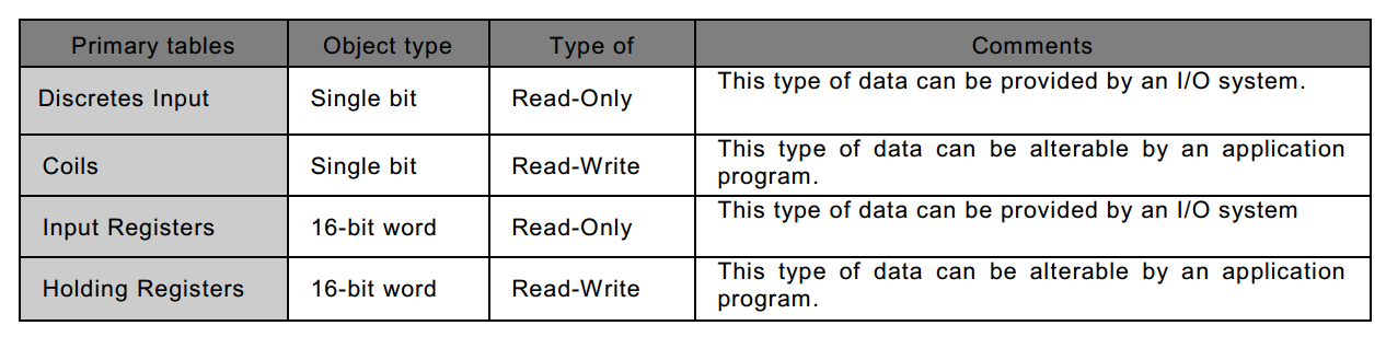
Figure 3. Taken from the Modbus Protocol Specification
For each type, a maximum of 2^16 (65536) data items can be located in a device's memory. There are specific function codes for accessing each of the different data types, with each type often having its own dedicated block of memory.
To address a data item, a master simply uses the range from 0-65535. Data item 1 would be located at address 0x0000. Data item 2 would be at address 0x0001. Data item 65536 would be found at 0xFFFF. Keep in mind, devices aren't required to have all 65536 data items; in fact, most remote I/O terminals that use Modbus will have far below this maximum limit.
Modbus Transactions
With an understanding of how data is represented in Modbus, we can now examine the transactions in detail. This will be from the perspective of the PDU, since the PDU is communication-layer-independent.
Modbus transactions use hexadecimal character instructions, where a single 8-bit byte is of the 0x00 format, with a range of 0-F for each character. A 16-bit register, then, is equal to two bytes, represented in the 0x0000 format.
The Modbus specification defines three types of PDUs:
- Modbus Request
- Modbus Response
- Modbus Exception Response
The master initiates a request by using the function code, while the slave sends a response in reaction to that request. A successful response echoes the function code sent to it by the master. An exception response replies with the same function code but with the msb (most significant bit) set high to indicate something went wrong.
There are a number of function codes defined by the Modbus specification. Function code 0x01 is the Read Coils function.
Figure 4 shows an example of what a Read Coils request and response might look like. The Modbus master sends a request with function code 0x01 (Read Coils) starting at the first data item (address 0x0000) and reading only a single coil. The Read Coils function can be used to read up to 2000 (0x7D0) coils at once.
![]()
Figure 4. Read Coils Transaction
If successful, the slave responds with the same function code and a count of the number of coils it's replying with. The coil status will be n bytes wide with each bit representing whether that particular coil is ON (1) or OFF (0).
In this case, the coil at address 0x0000 is ON. Had the request not been successful, the exception response would contain the function code with the msb set high (0x81) along with an exception code that explains what went wrong. Exception code 0x02 means that an illegal data address was used, i.e., there is no coil at 0x0000 in this slave's memory.
The next example illustrates a Write Single Register transaction (function code 0x06). Here, the master requests a write of data 0xA0A0 to address 0x00FF. The slave's response is simply an echo of the request.
The example exception response here shows the function code with the msb set high along with an exception code of 0x04. This code means that an unrecoverable error has occurred while the slave was attempting to perform the request.
![]()
Figure 5. Write Single Register Transaction
All Modbus function codes follow a similar pattern to the two examples shown above.
Figure 6 shows a list of the common function codes along with exception codes for exception responses. For more information, consult the Modbus specification.

Figure 6. Function Codes and Exception Codes
Conclusion
Modbus allows PLCs to communicate with all kinds of remote units, including I/O banks, terminal units, and other controllers, by relying on a standard method to read and write both discrete and integer information, covering nearly every scenario that involves the transfer of digital data.
Modbus is a standard in the industry today and represents the most widespread royalty-free industrial protocol to date, despite the fact that it pre-dates most modern control systems. It can be found throughout plants and factories around the world, and despite its longevity, is sure to remain a relevant industrial protocol for many years to come.