Facebook
 Google
 GitHub
 Linkedin
Analog vs. Fieldbus Systems | Comparisons and Advantages
Learn about electrical signalling systems for process control. What advantages may be provided by choosing analog systems vs. advanced modern fieldbus protocols?
Early manufacturing facilities didn’t rely on any type of automatic controls; all of the processes were based on manual operations, using human interaction to start or stop every part of the process.
Electronic instrumentation gradually replaced mechanical and pneumatic legacy instrumentation, and many familiar signal standards began to emerge, such as 4-20 mA current loops or 0-10/0-5 volts DC.
In this article, we will discuss the most common types of instrumentation signal ranges, where they are used in industrial applications, and their strengths and weaknesses.
Overview of Current and Voltage Signals
The traditional 4-20 mA loop current is widely used in the industrial control system for process control. It is also called a live zero, because the 4 mA minimum signal corresponds to a 0 (or minimum) of the actual process value, like current, voltage, flow, speed, etc. The maximum signal is 20 mA, representing the maximum process value range. The live zero standard helps maintenance field engineers troubleshoot open-circuit faults quite easily, such as a broken wire, when the signal actually drops to 0 mA.
The other common signal type, 0-10 V DC, is acceptable for many applications, but according to Ohm's law, in a series circuit, the voltage drop increases across long-distance wires, thus causing signal loss. If the transmitter is located near the process, but far away from the controller or RTU, the mA signal works best. It is a good option for long-distance applications compared to the voltage signal.
In Ohm’s law, V (the voltage drop) equals the product of I and R. In the signalling circuit, the voltage drop equals the current multiplied by the resistance of the wire. The resistance (R) in the circuit increases as the wire grows in length. A local transmission from one panel to another nearby I/O panel, or an analog sensor connected to a nearby controller; these are both good applications for a voltage signal.
In recent times, many microcontrollers and digital I/O boards require a 1-5 volt DC signal, but a 4-20 mA signal is preferred in the industry. For ADCs in RTU/PLC/controllers, a 250 Ω resistor is installed on the receiver end or the connection unit to convert a 4-20 mA signal into a 1-5 volt signal.

Figure 1. Conventional 4-20 mA current loop wiring in the terminal box. Image used courtesy of the author
Advantages of mA/V Signal Systems
- Simplicity: A handheld multimeter can be placed in series to measure the loop current and across the circuit to measure voltage in the circuit for reading and troubleshooting.
- Live zero: The 4 mA signal confirms that the signal wire is not damaged or broken.
- Slow changes: A digital signal can be superimposed over a 4-20 mA loop current, therefore supporting the HART protocol.
- Safety: Service engineers can work on these live circuits, in contrast to high-voltage load circuits.
Disadvantages of mA/V Signal Systems
- Individual signals: Separate cables and wires must come from each transmitter and transducer to the I/O interface panel, RTUs, or PLCs; consequently, adding more wiring and manpower installation costs during the project.
- Complexity: Future extension to add new signals is not flexible due to the need to change and shift the wiring plan.
- Information limits: Only basic analog quantities (4-20 mA) can travel on a wire to report measurement, and no digital communication; it does not support the reporting of device health and status for remote diagnostics.
- Configuration: Remote configuration of field devices is not possible. Calibration must be conducted at the device.
Foundation Fieldbus Protocol
A fieldbus is a digital communication for the exchange of data between the sender and receiver. Foundation fieldbus is an industrial protocol that falls under the category of digital protocol and has become a standard for process control, enabling multiple devices to communicate at the same time on the digital highway.
The terms sender and receiver could be used for the host, i.e., PLC, IED, RTU controller. The foundation fieldbus not only sends telemetry data, but it also transmits diagnostic and device health data. From a maintenance and troubleshooting point of view, the service engineer can easily connect remotely from the control room to the fieldbus device for adjustments, such as the span.
For process application, the common fieldbus protocols are HART, PROFIBUS, and Modbus, etc. As compared to the conventional 4-20 mA system, a fieldbus reduces the number of wiring connections.
It is witnessed in legacy 4-20 mA devices that separate cables must be routed to the control room or the RTU/PLC marshaling panel for each device. Fieldbus devices can all be connected to the network in a bus or star topology, and a single cable routes from the junction box to the control room to the controller device.
As per Figure 2 below, multiplexers are installed in the junction box. The role of a multiplexer is to convert several input wires into a single, selectable output wire, called a spur. The spur is a wire on which the power supply and communication signal are supplied. In practice, multiple multiplexers are installed in a junction box. The multiplexer could be an 8-channel to accommodate several RTDs.
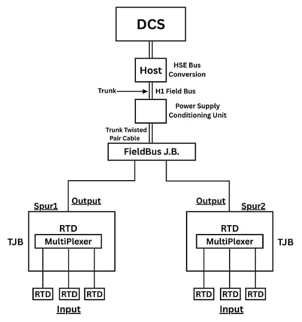
Figure 2. Fieldbus topology consists of a spur and a trunk. Image used courtesy of the author
While discussing the fieldbus protocol, there are some well-known terms like trunk, spur, terminator, H1 bus, and HSE bus, which are the fundamental parts of the foundation fieldbus implementation.
Trunk: The main communication bus, acting as a source for other spurs.
Spur: The branch cable used to connect the field devices to the main trunk.
H1 Bus: Also called the fieldbus, the purpose of the H1 bus is to connect field instruments (RTDs, sensors). For both power and communication, 2-wire twisted-pair cable is normally used.
HSE Main Plant Network: Higher-speed Ethernet for plant-wide communication
HART Protocol with Advantages
HART stands for Highway Addressable Remote Transducer. In the field of control and instrumentation, HART is a well-known open standard protocol. An open standard means it gives freedom to every vendor to use it in their device.
HART protocol is a hybrid protocol in the sense that it uses analog and digital communication over the same analog wires used for conventional 4-20 mA signals. Therefore, an additional digital signal can be superimposed using Frequency Shift Keying (FSK) on the 4-20 mA signal for additional information acquisition. The additional information could include the device tag, range, span, and the measurand value.
HART is a bidirectional, half-duplex communication type and transmits data with a baud rate of 1200 bits per second. The digital signal operates on 2 different frequencies: 1200 and 2200 Hz. The 1200 Hz frequency is taken as bit “1/High” and the 2200 Hz is interpreted as bit “0/Low”.

Figure 3. HART protocol communication between master and slave. Image used courtesy of the author
HART systems possess some of the following advantages over conventional current loop system.
- Open and accessible: It is an open standard, hybrid system that supports analog and digital signals using the FSK principle.
- Remote access: Enables the field technician to perform remote calibration and diagnostics.
- Upgradability: Using the HART protocol, we can easily upgrade the legacy current loop system with no additional wiring, thus cutting the cost of additional wires.
- Process and diagnostic data: The usage of diagnostic data and logs helps in predictive maintenance.
Electrical Signal Systems
As technology evolves, there is no clear advantage of one system over all others. Each signal system is used for specific reasons, and many facilities contain a mix of several different practices all in support of the main mission of data collection and control of actuators from a reliable central control system.
Featured image used courtesy of Adobe Stock
Related Content