 Facebook
 Google
 GitHub
 Linkedin
Developing Standardized Practices for PLC Programming
Any kind of computer programming can be challenging to determine what aspects are truly unique versus what aspects should be standardized across projects and platforms to streamline future development.
Similarities in Machine Design
A machine builder is a company that designs and builds automated equipment or integrates pre-defined components into a complete assembly. This automated equipment is designed with the client's process and product in mind, so for this reason, the client is heavily involved in the design phase of the equipment.

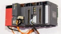
Figure 1. PLC code development can be a time-consuming process with no consistent in-house standards in place. Image used courtesy of Rockwell Automation
Once the mechanical and electrical design is complete, the control engineers take over and begin to develop the PLC code that will control the equipment. A PLC typically controls the equipment with a local code running inside the CPU. Often, the PLC code is similar between projects, so a standard can be developed to save time during the project's initial phase.
Developing a standard requires analysis of the industry and the type of projects handled by the engineering/design company. After discovering the similarities between projects, the engineer can design efficient, well-thought-out code so that users of the standard can easily and quickly re-deploy the standard onto new projects.
There is no universal PLC programming standard—these common similarities only exist across related functional projects, like a company that only designs palletizers or only creates SCADA systems for energy management.
The first step to developing a code standard is to identify the similarities between your projects. The below points are some common functions that I have come across in my own work experience.

Figure 2. Distributed I/O devices, with consistent tag layouts and terminal quantities, can speed up the development of a system. Image used courtesy of Festo
Common Inputs and Outputs for PLCs
Every project will have some kind of input and output, no matter the type of control system being used in the project. Thanks to fieldbus technology like Ethernet/IP, PROFINET, and EtherCAT, mapping I/Os has become a simple and easily repeatable process.
Some companies like to standardize the type of remote I/O used on projects so that the design can simply be copied and pasted into the new project. With PLC code, that is not always possible. For I/O, it’s best to target the popular fieldbus technologies and have a couple of examples that can be referenced.
Whichever remote I/O you are using, it is best to map the inputs and outputs into a user-defined data type. This makes it easy to reference the usable inputs and outputs by name rather than by address. With Allen-Bradley (Rockwell) PLCs, the Ethernet module tags can be copied into a tag provided that the user-defined data type (UDT) is the same size as the source tag. This method maps the I/O with one instruction, and UDTs can be created from Microsoft Excel.
Some systems can have hundreds, if not thousands, of inputs and outputs, so developing a standard way to map those tags to usable tags will greatly reduce the amount of time you spend in development.

Figure 3. Large machine centers, with robots, controllers, and many I/O devices, require careful attention to detail in order to standardize any process. Image used courtesy of Unsplash
Standard Automation Sequences
A sequence is a series of events that occur in order, and PLCs are great at handling sequences. Just about every automated assembly machine or equipment will have sequences. Typically every station within a cell could have multiple sequences that run in parallel. Most machines heading out the door will have one or more sequences, so it’s a good idea to develop a standard way to write the sequence.
There are many ways to sequence events in a PLC. Some manufacturers offer special function blocks that will control your sequence or aid in writing a sequence subroutine. Siemens TIA Portal has a graphical sequencer called a graph, and Allen Bradley offers a sequencer that compares individual bits within a word; when input conditions set individual bits, resulting output bits are set.
You could also create your own sequencer by simply moving integers (10, 20, 30, and 40) into a tag once certain conditions are met and then comparing the previous sequence step with the current step. Choose a sequencer that is simple to understand and debug. Some people do not like using built-in sequencers because there are actions happening behind the scenes, which makes it hard to troubleshoot. Also, make sure your sequencer can be scaled easily—as your projects grow in size, so will your sequencer.
Faults and Warnings
Faults or warnings are ways to inform your operator of issues within the machine or a process that is taking a long time to complete. For this reason, every machine will have faults and warnings. Most HMI applications will have built-in methods to display faults, but if you develop a standard using built-in methods for a specific application, then a new customer wants a different HMI application, your standard is at risk of failure.
A common method of faults and warnings is to generate a number for each fault or warning. This can be done by converting a binary address to a number or by moving a number into a tag. This number is then sent to the HMI application via a mapped tag, and a text string is then mapped to the number. When the HMI detects a number on the fault tag, the fault is displayed. Within the PLC code, you will also need to make sure the machine stops when a fault is registered.
Machine Control Similarities
Every machine will have a similar control—you will need to start and stop the machine, put the machine into different modes like manual or automatic, and the machine will need to stop if a fault is generated. This control functionally should be developed very carefully—there is nothing worse than a machine that is stuck in a mode and not producing parts or a machine that won't start and there are no faults. I like to break the machine control into small components, analyze your cell and break it down into operations or stations. I like to make each cell its own program, and each station is a subroutine within the program. There is a main cell control program for the entire machine, and the cell control gets passed into each station. The status of each station is passed back out to the main cell control. By using this method, your machine can grow or shrink without affecting the overall structure of the code.

Figure 4. Implementing coding standards requires process observation and documentation well before writing the first program command. Image courtesy of Adobe Stock
Benefits of PLC Code Standards
As you can see, there are some rather large sections of code that could be standardized and then redeployed to other projects. By developing a standard, you not only save time on the next project but also make servicing the equipment easier.
Equipment that has been in service for a few years will eventually need to be serviced; likewise, if the customer is requesting additions be made to the equipment. By having a well-developed code standard in place, any control engineer within the company should have fewer problems familiarizing themselves with the code and tracking down the root of the problem quickly. While developing PLC code does take quite a bit of time, it should be considered an investment within your company because, ideally, you will be able to complete projects faster and support existing projects more efficiently.
Related Content


Low level standardization tends to enforce lock in. Truly useful standardization would be brand and platform independent. For example a state machine can be implemented on almost any controller. The differences between brands and tools make standardization a tall order. In a standardized world, conversion to another brand wouldn’t be a major rewrite project. I won’t hold my breath.
I’ve been holding my breath on this topic too long. That’s why I decided to do something about it by publishing the PLC Code & Standard, a field guide for PLC programmers and those who work with them later this year. There are way more benefits to applying a standard than just saving time on your next project and making servicing easier: A standard should lead you to think about how things are done in you controllers and why. For instance the I/O mapping that was talked about should do more than just copying the raw module tag to a named UDT. I/O conditioning involves decisions on treating all I/Os of a given type the same. What signal conditioning is applied, what diagnostics are applied, what alarming. How is the programming done in the best way to make access quicker, depending on what is driving the access - the tag name or the drawing/documentation reference. What sort of standardization do you apply to the tag name itself, and then the descriptor. And all of it needs to be responsive to your plant, your project. Well, if you work in this field you know its needed, but nobody wants to put in the work just to show the competition how it needs to be done, or see it ripped off just like current engineering standards are. I guess that why I had to wait to get near retirement before I put all my notes from the past fourty years of working in this field together in a formal way. If you are interested you should go to plc-control.com and express your interest.