 Facebook
 Google
 GitHub
 Linkedin
The Spectrum Between Human and Machine: The Industrial HMI
Although ‘HMI’ has become synonymous with a durable, rugged touchscreen measuring 7 to 21 inches and mounted in a control cabinet door, the reality of the interface extends far beyond this device.
The human-machine interface (HMI) has become synonymous with touchscreens and full-color dashboards, seen on virtually every control cabinet and operator station around automation equipment.
If we dig into the real definition, the interaction between equipment and operators actually extends far beyond those fancy display screens. A properly designed control system (or a properly retrofitted system) will likely include multiple layers of sensors, controls, and hardware, and it is up to the system engineer to choose the right components accordingly.
The various types of interface may be referred to as ‘layers’, with each one representing a more tech-centric degree of harmony between the physical and virtual world. Here is a breakdown of the present layers that exist in today’s manufacturing world.
Layer 1: Manual Controls
The first type of HMI is the most basic: purely manual inputs. By definition, buttons, switches, joysticks, and other such devices represent a true HMI (interface between humans and machines). Often, these devices are binary, outputting an on or off state, but sliders, knobs, dials, and other such components allow for analog control.
At first glance, manual controls can seem outdated. However, some systems benefit from such controls. Consider a piece of industrial equipment that poses numerous safety hazards. There should be an emergency stop button within arm’s reach at any point in the machine. This E-stop should be a physical button, not a software button that is vulnerable to software crashes, but instead a physical disconnect.
Other physical buttons, switches, lights, and alarms provide tactile, visual, and sometimes audible feedback to the operator, giving more confidence that a process sequence has occurred.
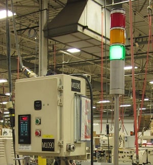
Figure 1. The stacklight is a purely manual signal, notifying operators of machine status. Image used courtesy of Wikipedia
Layer 2: Manual Data Entry
After manual controls, there is a layer of slightly elevated sophistication: manual data entry. In this HMI layer, data is collected by a human operator and then manually entered into a control system. Perhaps a flow reading from an analog gauge is entered into logging software for archival or troubleshooting purposes.
In many cases, this layer can be eliminated through automated sensors and hardware, and most often, it should be. Sometimes, the economics do not support this; retrofitting the system may be too expensive or cumbersome. Also, this does give operators the chance to verify and qualify the data coming from the sensor directly. Sometimes, when a process is automated, creeping issues only become apparent when there is a major problem.
Layer 3: Displays and Dashboards
Stereotypically, when someone thinks of HMI, they think of displays and dashboards, like a regular industrial touchscreen display. While that is only one part of HMI, it is a critical part. A well-designed dashboard is a science better left to other articles, but in general, it will display only the controls and data that are required, and these items will be organized in a standard fashion with unambiguous labels. Buttons will always have the same format, and key functions will be located in the same place across dashboards.
One of the key benefits of displays and dashboards is the ability to customize the data that is displayed. For control room operators, they can log into a computer or desktop and see exactly the data they need for their job- and nothing else. This helps reduce errors in analysis by not cluttering up their vision with figures they do not need, as well as protect trade secrets by only allowing access to relevant data to their specific job role.
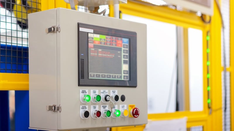
Figure 2. A classic industrial HMI. Image used courtesy of Adobe Stock
Layer 4: Sensing and Control Loops
Many processes benefit from full automation. In these cases, sensor data is recorded and used in a feedback loop, where the data is used to adjust a process parameter and ultimately change the value of the data. In these fully automated loops, human interaction is limited to fine tuning of the process control loop. Once the feedback loop has been established, the process is largely “hands off.” Even in modern systems, the HMI may be nothing more than a small 7-segment display with only a few buttons for adjusting settings or parameters. Examples can include PID controllers or even HMI panels.
In the modern era, this is where we might introduce machine learning (ML) and artificial intelligence (AI). Both of these can lessen the load of tuning for these feedback loops. Furthermore, the tuning itself can be adjusted over time as patterns emerge in the data.
The use of ML/AI in a fully automated control loop is a powerful tool, but it still requires the engineer to examine the predicted results. Contact with the machine is minimal, but it is not eliminated entirely.
Layer 5: Machine Vision
Machine vision is an ever-expanding field. As higher resolution cameras with better detection routines become available, many industrial sites are using machine vision to monitor processes affordably.
One of the unexpected benefits of more robust machine vision is the ability to retrofit what was formerly too expensive to retrofit. Many chemical plants rely heavily on manual gauges that are simply too important to take out of service or too expensive to reliably automate. First, they installed cameras so that operators in a control room could monitor their readings remotely instead of having to walk out into the plant. Now, thanks to machine vision, the images of those gauges can be analyzed for trends. No new sensors or plant downtime required.
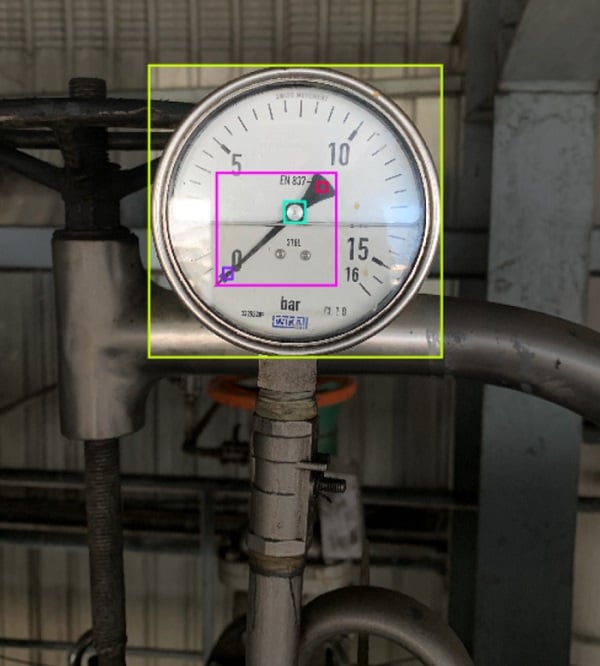
Figure 3. Machine vision systems track the position of the needle in this analog gauge. Image used courtesy of Universe Roboflow
Real Hardware Systems
Chances are, most hardware systems are not fully integrated. Even if they are, they will likely contain a mix of these HMI layers scattered as appropriate throughout the facility. The reasons for different layers vary. Two separate systems may not communicate, requiring an operator to enter values from one system into another. Analog gauges may be monitored with machine vision, and a valve manipulated with a full control loop managed by the visual input. There are countless other reasons.
As the design engineer, it is essential to understand each of these layers, how they interact, and where the pain points exist. Communication problems, frequency of operator errors, necessity of specialized training, and so on help identify the places where integration between layers could be smoother.
The Future of HMI
New sensors and smarter ML/AI and machine vision algorithms will continue to push systems towards full automation. This has the potential to reduce scrap and rework, enhance safety, and boost throughput. It is also an important method for addressing the labor shortage by decreasing the amount of training time required to operate the system. However, this is contingent upon a proper understanding of how all levels of HMI work, and performing a cost-benefit analysis when choosing equipment.
Related Content


I share the same general idea, but I would emphasize one additional point:
the HMI should not only serve as an interface between the human operator and the PLC,
but also as a controlled interface for an external “software operator”.
The traditional rule that the PLC must keep the process running safely without relying on the HMI is absolutely correct.
The HMI should be limited to parameter input, visualization, operator interaction, and status indication.
The PLC should remain deterministic, simple enough to verify, and responsible for all basic real-time and safety-related control functions.
However, in complex production systems, the effective control loop is often not just PLC + HMI,
but PLC + HMI + operator. The operator observes the process, reacts to deviations, compensates for process uncertainty,
and adjusts parameters based on experience. In many cases, this improves product quality,
but it also introduces human error, fatigue, and unpredictable reaction times.
Some of these operator functions can be partially automated by an external software module.
This module may use a process model, optimization algorithms, statistical analysis, machine learning,
or other methods that are difficult or impractical to implement directly in the PLC.
It should not replace the PLC or become part of the critical real-time control layer.
Instead, it should interact with the machine through a clearly defined HMI/API layer.
In this architecture, the HMI becomes not only a visualization and command interface,
but also an arbitration layer between the human operator, the PLC, and the external “software operator”.
It should clearly show who is currently controlling the process, which mode is active,
and whether the external algorithm is only providing recommendations or actively applying corrections.
The most important requirement is safe and transparent handover.
The operator must be able to take control back at any time,
and switching between manual, automatic,
and software-assisted modes should not cause sudden jumps in process parameters or unexpected machine behavior.
This approach keeps the PLC reliable and deterministic, keeps the HMI stable and understandable,
and allows advanced operator-assistance algorithms to evolve faster without compromising the basic safety and reliability of the machine.
In other words, the HMI should not be treated only as a screen for the PLC.
It should also provide a controlled and transparent interface for software modules
that take over part of the operator’s role in complex but non-hard-real-time tasks.
This is especially useful where a simple PID loop is not sufficient, while implementing the whole logic directly in the PLC would make development,
testing, and future improvements unnecessarily slow and difficult.