 Facebook
 Google
 GitHub
 Linkedin
Intro to PLC Programming with Rockwell’s Studio 5000 and CompactLogix
Rockwell Automation is known for being one of the most popular PLC brands, supported by many compatible devices. Learn the basics of getting started with a CompactLogix project in the Studio 5000 environment.
Rockwell Automation is well-known for the production of popular control systems as well as the driving force behind the Allen-Bradley brand of hardware from motor drives to I/O devices and controllers for many decades.
The most recent evolutions of Rockwell’s PLC development environment, Studio 5000, provide advanced capabilities to design automation systems from simple machines to complex, vast networks.
In this tutorial, we will set up a basic project in Studio 5000 for a particular CompactLogix controller and establish an Ethernet connection for a very simple program.
An included video at the end introduces the same tutorial, so you can skip down to the end if you prefer the video format.
Start a New Project
When first opened, Studio 5000 allows you to begin a new project, choose from a list of existing projects, or begin with the project already stored in an online controller.
NOTE: the terms project and program, although similar, should be distinguished. One project may contain multiple programs, but a project is downloaded and executed in a controller.

We’ll begin with a new project. When we choose this option, we’re represented with a list of compatible controllers. Some versions of Studio 5000 will be compatible only with certain controllers. This version happens to be Studio 5000 Lite, which is compatible with the CompactLogix line of controllers.

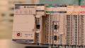
I will use my personal PLC of choice, the L16 with Ethernet and embedded I/O terminals for easy configuration.

Project details are the next selection. Firmware revision in the project and in the actual physical controller must match. If they don’t, you’ll either need to flash the firmware of the controller or download the correct software revision.
This PLC can have Point I/O modules for expansion, but I won’t use any for this project.
FInally, security details can allow only certain computers or users to access this PLC to prevent unauthorized access.

Creating a Ladder Logic Program
Once inside the newly-created project, we can begin to build a new program, specifically, inside a ladder diagram (LD) routine.
In the project view, a new Main task will contain a Main program, with a Main routine. Open this Main routine to access the ladder logic.

To build a very simple ladder routine, we find the default instruction list at the top-center of the screen, with some rung and bit instructions already filled in.
We’ll click and drag one Examine On (also called XIC) and one Output Energize (OTE) into the rung, to the left and right sides, respectively.

We will end up with a rung that looks like the following.

Addressing Instruction in Studio 5000
Before going further into programming, we should take a moment to see how the instructions are mapped to the physical devices in the real world.
This happens in the tag listing. When you first created the new project, the built-in configuration tools already know how many I/O points are fixed to this PLC, and how to access them. That means that the addresses already exist…somewhere.
They are found in the ‘Controller Tags’:

Base Tag Addresses
Local indicates attached to the controller: 1 is a slot designation, and while this embedded module has no actual slots, the CPU is considered slot ‘0’ and the I/O is in slot ‘1’.
‘I’ gives us input data, while ‘O’ gives output data.
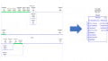
As you can see from the following image, the addresses follow a format of Local:1:I/O.Data.0 through 15.

I’ll attach a button to the first input terminal and a relay to the first output terminal, so my base addresses are Local:1:I.Data.0 and Local:1:O.Data.0.
Alias Tag Addresses
Perhaps a more convenient tagging method is to assign a user-friendly name to a tag. In my case, ‘Button’ and ‘Relay’ might make more sense.
If I access the ‘Edit Tags’ menu from the bottom of the screen, I can make a new tag called simply ‘Button’. The next column ‘Alias For’ is a place to provide the old base address, and they will be forever connected.

Then I’ll do the same for the relay.
Now I can go back to my Main routine and simply use ‘Button’ and ‘Relay’ as the instruction names.

Download the Project to the Controller
We can choose to connect via USB or Ethernet. I’ll connect through USB in this tutorial, with a follow up addressing the configuration and connection of the Ethernet network.
USB Connection
Make sure you have the PLC powered on with a good data cable. This model uses a USB type-B like a printer.
Use the ‘Select Communication Path’ button from the top and find the USB device from the menu. You can ‘Set Project Path’ here once the device is connected.

The nice thing about USB is that no addresses are required, it’s only a 1-to-1 connection. If the PLC is connected, it will appear in the menu.
Download Project to Controller
Once you set the project path, it’s possible to download right from here, but it’s also useful to know how to find the download option from the ‘Communications’ menu.

Select this option, verify the confirmation warnings, and the program should smoothly download.
Remote Run Mode
Once the program is running, be sure that it’s in Rem Run (remote run) mode, with green showing in the upper right corner.

Once the program is running successfully, the output will successfully energize when the input is also energized.
Be sure to check out the next tutorial where we uncover analog I/O signals and Rockwell's Point I/O device family.
Tutorial Video - Studio 5000 Project Setup
Want to test your knowledge of PLCs? You think you N.O. a lot about ladder logic? Are you a normally-open or normally-closed minded engineer?
Check out our PLC Programming worksheet!


I still have nightmares 15 years after having worked with RSlogix… The software itself is alright, but the versioning system was horrible, and getting it to talk to RSlinx, an dalso using RSLogix500 was just horrible, if you updated any part of one, you had to update everything, and this was true with minor version changes. I did do some cool stuff with it though
Well done on this, David. Gives a great start with such a complicated program. I also have the same thoughts as Rx7man since it is a chore and ordeal to link to any Rockwell PLC for me with this key status and revisions. Nightmarish!