Facebook
 Google
 GitHub
 Linkedin
Rockwell’s Studio 5000 and Analog I/O Tutorial 2
Learn how to install and program analog modules into Rockwell’s hardware and software environments using a CompactLogix PLC and Studio 5000.
Check out the first installment of our tutorial series:
Analog devices are used to measure process values that have a range of values. Many inputs have only ‘on’ or ‘off’ as the possible values, like a sensor to detect an object or a pushbutton to indicate a user on/off input. However, most processes rely on at least a few variable signals that must be examined to determine how the system should respond.
What is an Analog Signal?
This question is answered in two ways, both of them important to the PLC.
First, the analog signals in the environment are those ones which have a minimum and a maximum, and more in between. Most natural ‘real-world’ signals are actually analog: light, heat, pressure, flow rate of a fluid, etc. We must know these values before calculating an output signal.
Second, the digital equivalent of an analog signal is a number that is stated as an ‘??-bit’ A-D converter—many common ones are between 10 and 16 bits. This number is called the ‘resolution’, and it refers to how precisely we can measure the value as it climbs and falls.
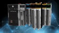
For reference, the analog input modules we will use in this project today are Rockwell’s Point I/O number 1734-IE2C which are 2-channel analog inputs for current. They are rated with a 16-bit resolution for signals between 0 and 21 milliamps.
An included video at the end introduces the same tutorial, so you can skip down to the end if you prefer the video format.
Starting a Project
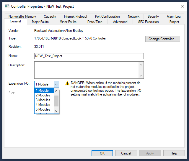
Beginning a new project was addressed in the first article, Studio 5000 Tutorial 1. When the project is created, you can choose the number of additional expansion modules. This is similar to choosing a base with a certain number of slots in chassis-based systems.
We can also add new modules directly from the project tree itself, from the I/O Configuration menu at the bottom left side. We can examine the properties of the I/O Expansion Modules and choose to add some into an existing project.
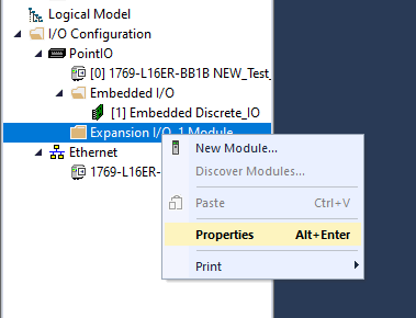
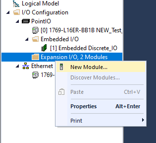
From here, let’s add two module slots so we can explore analog inputs and outputs.
Once the slots are added, we can select the right modules to fill them. (By the way, this is not literal slots like in chassis, but rather virtual slots so the CPU knows how many modules to address)
I’m going to select a 1734-IE2C and a 1734-OE2C, these standing for input (I) and output (O), analog (E), with 2 channels (2) for current (C) from the 1734 Point I/O series.
If you are adding modules to a modular CompactLogic L3x CPU, the family prefix will be 1769, if it’s a ControlLogix, the family prefix will be 5570/80, although different generations of these groups may have different family group numbers.
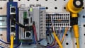
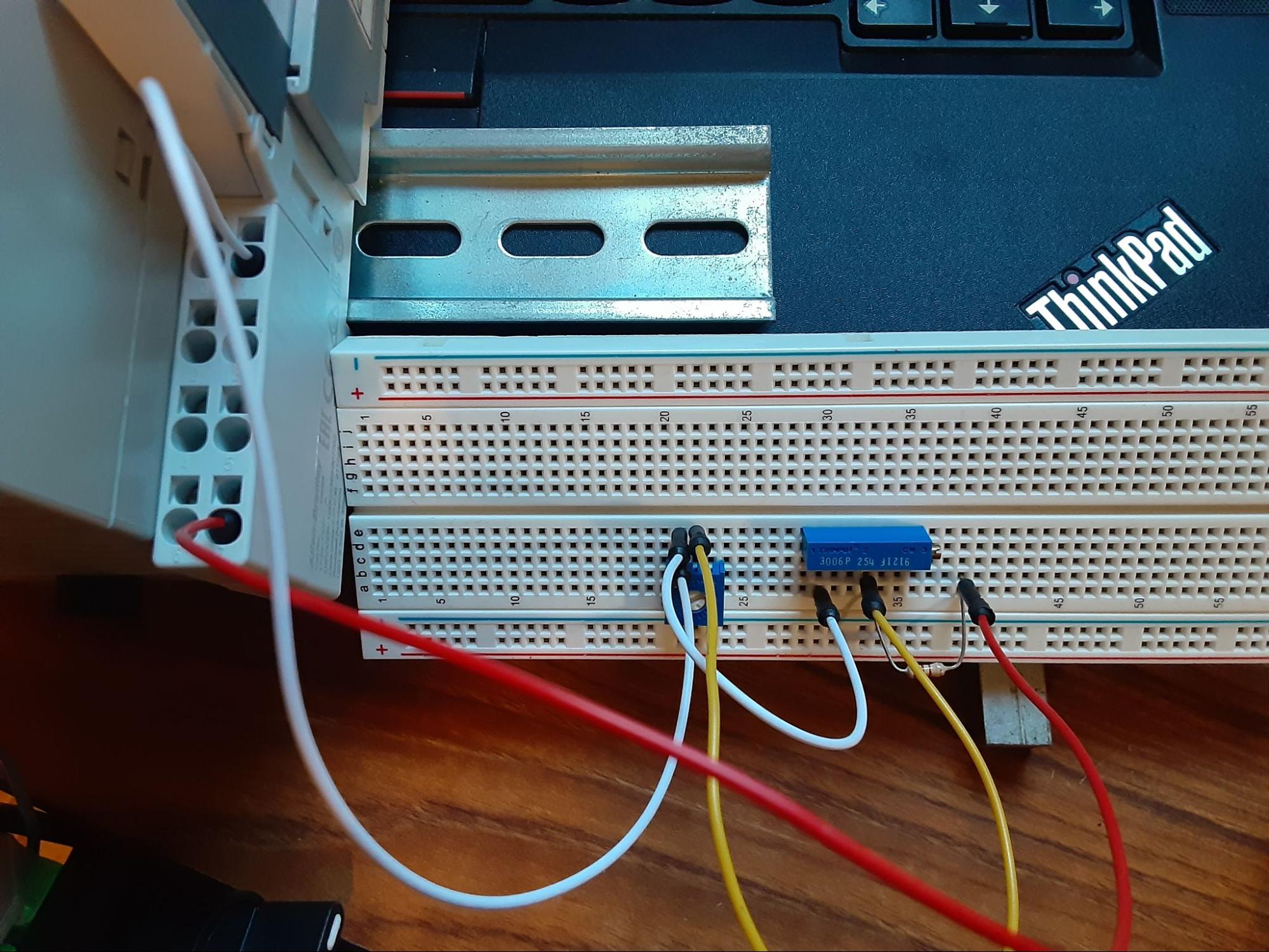
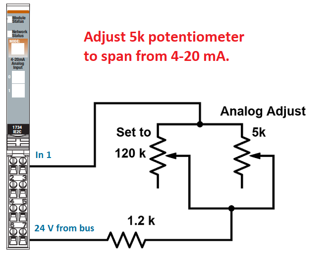
For my input circuit to simulate a sensor with a full range of input values, I have designed a simple resistive circuit on a breadboard with a 1.2 kΩ fixed resistor in series with two adjustable resistors placed in parallel. These resistors are 5 kΩ and 120 kΩ, respectively. As the 5 kΩ resistor is adjusted, the total circuit resistance spans from 1.2 kΩ to 6 kΩ, which, when supplied with 24 volts, provides me nearly 0-20 mA of current. They are not precisely adjusted, but the span is entirely sufficient for ease of demonstration.
The following images illustrate the physical wiring and the schematic representation with connections to the 1734-IE2C module.
How to Scale Analog Inputs in Studio 5000
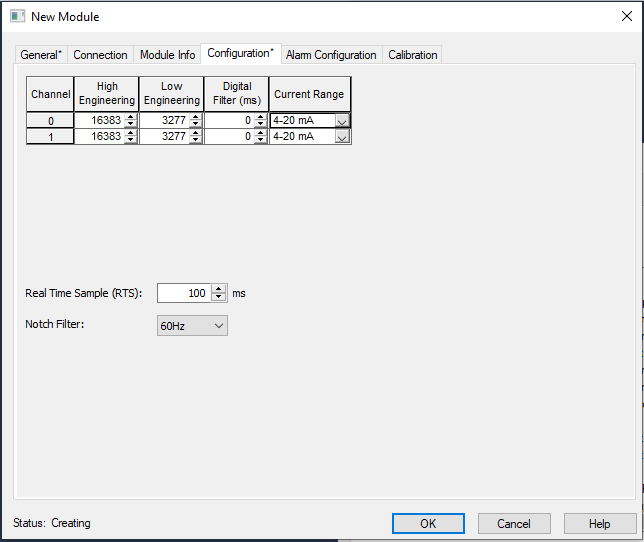
In the configuration tab of the new modules, we can see the engineering values, both high and low. Because of the signed integer’s 16-bit value, only the positive half is allowed for positive current values. So the total range of the current value input is 0 to 16535. However, there is a small amount reserved below 4 mA and above 20 mA to be used in alarm situations, therefore, the total default range of a 4-20 mA signal is 3277 to 16383, as seen below.
The Rockwell software gives us the ability to select our own values to be considered ‘min’ and ‘max’. This is pretty useful because the actual incoming signal relates to a tangible quality. For example, if this is an analog distance sensor, the max value might be 30 inches, while the minimum value is 2 inches. Showing a 14,000 on the programming screen might not mean much to an untrained operator.
For this example, assume that our sensor is indeed an ultrasonic distance sensor with a metric sensing range of 0-800 mm (about 30 inches or so). I can simply provide those values into my channel 1 input (which is where I have installed my simulated sensor).
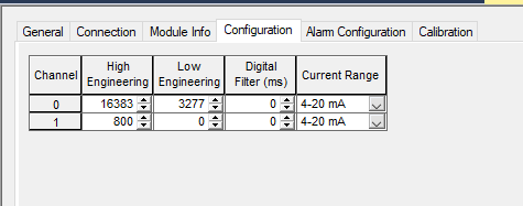
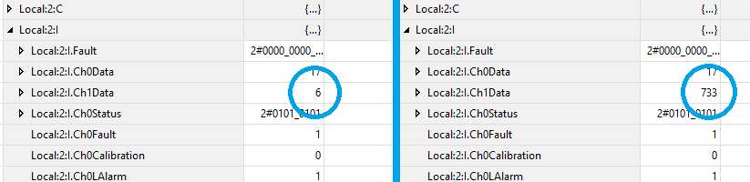
Once this change is downloaded, the value in the controller tags now spans from nearly 0 to 800, as the image below shows, to the left and right sides, respectively.
One additional note about scaling inputs may help remove confusion.
Changing the High and Low Engineering values of the module do not affect the current input in any way at all. I switched the values from the default to the new adjusted values and downloaded the new configuration while the module was running, all without changing my circuit.
Programming with Analog Inputs
Using the analog values in a program is simple with an understanding of integers. This analog value tag, Local:2:I.Ch1Data is indeed a 16-bit INT.
We cannot use bit commands, such as XIC and XIO with analog values, but they are very useful in any mathematical conversion or inequality instruction. Such guides can be found in abundance, including these articles covering Math Instructions, Comparison Instructions, and Trigenometry Instructions.
Configuring and Programming Analog Outputs
If the engineering limits for the analog inputs made sense, the outputs are designed with the same strategy in mind.
An output module will supply a range from 4-20 mA (for this module, or a voltage range for other models), but it’s helpful to determine the real-world value for what each output might represent.
Let’s assume we wish to drive a variable frequency drive, where 4 mA corresponds to 0 Hz and 20 mA corresponds to 60 Hz, the full range of the motor drive output.
Since the OE2C has an output resolution of only 13 bits, the engineering range default isn’t quite as high as we saw for the input module. By default, sending 8191 (which is just below 2^13) to the Ch2Data tag will produce 20 mA, while sending 1638 will produce 4 mA.
But if 8191 is meant to drive the motor at 60 Hz, this is not immediately clear to most end users. Therefore, it might make more sense to scale the engineering value such that 6000 corresponds to 20 mA (which is 60 Hz) and 0 corresponds to 4 mA (0 Hz).
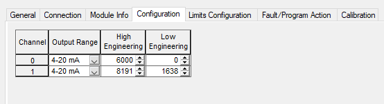
We could determine that the High Engineering could be 60, and therefore we are directly driving the motor frequency, however, this is such a low value that it would impossible to drive in fractions of Hz. Therefore 6000 = 60 Hz and the programmer can procesely drive the motor in increments of 1/100 Hz per count.
Sending Values to Analog Outputs
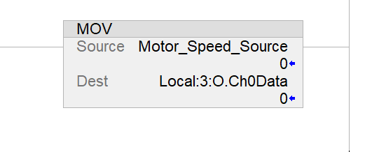
Once again, instructions with INT destinations are ideal for driving analog outputs. Such commands might include the DEST tag of math commands, as previously, or a MOV command, which is quite common.
Analog Values in Studio 5000
Since most of the world’s data exists in analog formats, it is critical to understand how to collect, process, and produce signals with variable values.
Tutorial Video - Studio 5000 Analog Scaling
Featured image used courtesy of Rockwell Automation
For further information about the instructions listed here, or programming of PLCs, be sure to visit our textbook and technical article library.
- Input/Output (I/O) Capabilities of PLCs
- Memory Maps and I/O Addressing
- Ladder Diagram (LD) Programming: Contacts and Coils
- Understanding PLC Program Commands: One-Shots
- PLC Program Commands: Storing Data Using Arrays