Facebook
 Google
 GitHub
 Linkedin
Tutorial: Analog I/O Programming for AutomationDirect Productivity PLCs
Learn how to use analog I/O devices with AutomationDirect’s Productivity series of PLCs and Productivity Suite software. Wiring, configuring I/O, and programming will be a part of this tutorial.
Discrete I/O programming is pretty easy with a PLC. There are a few initial hurdles to overcome, like understanding sourcing vs. sinking, PNP vs. NPN, and of course, normally open vs. normally closed (fortunately, there are plenty of resources to help with each of these obstacles). However, once these initial points are learned, the programming involves simple combinations of discrete contacts and coils.
But once we enter the world of analog, things tend to get more confusing. In this tutorial, we will use a Productivity1000 PLC from AutomationDirect to learn about wiring, scaling the inputs to proper engineering units, defining limits and understanding conversion ‘bits,’ and we’ll cover a few basic programming operations that provide much greater flexibility than coils and contacts alone.
PLC Analog Input (AI) Hardware
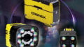
For our project, we will be gaining data from an analog ultrasonic sensor, used to measure distances. This sensor is a U-Gage T30 series from Banner Engineering, and it actually provides both analog and discrete outputs, although we’ll focus on the analog signal. This model provides a 4-20 mA teachable current range.

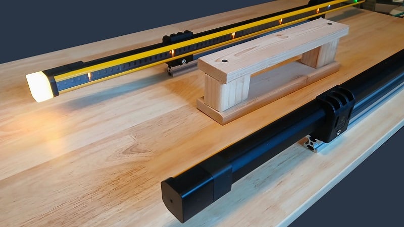
Figure 1. A training bench setup for practicing analog signals using an AutomationDirect PLC. Image used courtesy of the author
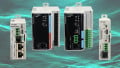
The PLC is a P1-550 from the Productivity1000 Series from AutomationDirect, a nice PLC for learning due to its relatively low cost and the free programming software. A combination analog I/O module is used, the P1-4ADL2DAL-1.
This I/O module has several key properties that are worth explaining.
Current Analog Input/Output
Analog signals are found in both voltage and current varieties. Voltage is much simpler, derived from a voltage drop across a variable resistance. They are common with potentiometers and other resistance-based sensing elements. However, constant current sensors are more suitable for industrial environments (this is a complex topic, read more here if you need to know).
This module has 4x analog current inputs and 2x current analog outputs.
13-bit vs. 12-bit Inputs and Outputs?
A more mysterious property of analog devices is the bit rating of the analog-to-digital (A/D) converter. Modules use integrated circuits that bring in a voltage and slice it up into many discrete ‘steps’. A 12-bit conversion has 4096 steps, while a 13-bit conversion has 8192 steps. More bits create more precision at the expense of a more costly chip, so it’s often not worth the money for more precision.
The inputs to this module have 13 bits of resolution, so over the entire input range (which is actually 0-20 mA for the module), there are 8192 steps.
Assume the sensor is measuring distances from 10 to 50 mm. Over this 40 mm range, we have a precision of (40 mm / 8192) just about 4.9 micrometers. Again, if we need greater precision, we must invest in a better input module. For my example, this is fine!
The outputs each have 12 bits of resolution across a 4-20 mA output range. If I wanted to use this output to, say, drive a VFD from 0-60 Hz, I can adjust the speed in increments of about 0.015 Hz, which is probably more than enough precision!
Low Input Resistance
Analog current inputs have a much lower resistance than analog voltage. Voltage sensors measure the voltage drop across a very large resistance to keep a very low input current. A typical input impedance for a current input device is over 100 kΩ.
In contrast, a current sensor increases its own voltage output in order to provide sufficient signal current, even if the load resistance is high. Therefore, the lower the load resistance, the lower the voltage demand from the sensor.
This module has an input impedance of 243 Ω per input terminal.
Wiring the Sensor
Now that we’ve spent a lot of time covering the basics, let’s wire up the hardware!
The module itself needs 24 and 0 volt supply connection from an external power supply, and the input current signal from the sensor. According to the wiring diagram, the sensor also needs +24 volts (brown wire) and 0 volts (blue wire), and the white wire from the M12 connector cable transmits the signal to PLC module I1+.

Figure 2. Wiring diagram for the sensor. The analog signal goes to I1+ on the PLC module. Image used courtesy of the author
Configuring the Input Module
We walked through an initial project setup for the productivity series in a previous article, so we will pick up at the Hardware Configuration section.
Adding the analog module is quite simple, we just drag and drop the correct module into the proper position. In my setup, I also include a digital input simulator for simple projects, but this is not necessary for analog signals.

Figure 3. Adding the module to the project hardware. Image used courtesy of the author
When we add the module, be sure to ‘Monitor’ the tag values so that we can see a live readout in the ‘Data View’ tab. This is important because, unlike discrete inputs, which trigger by a pre-determined event taught at the sensor, we must read the data to know what input values relate to what scaled output.

Figure 4. Adding the tags to the data monitor window. Image used courtesy of the author
Scaling the Real-world Analog Values
Some PLCs allow you to scale the engineering values right when the module is set up, but we can easily set it up in a single ladder rung, regardless of make and model.
But wait, first… What do we mean by engineering values?
There are a lot of numbers associated with these analog sensors. The original sensor output is between 4 and 20 mA. It’s going into a module built for 0-20 mA. The module A/D converter turns that into the 0-8191 value we discussed before. BUT STILL none of these numbers actually show us the information we need to know.
How far is the object away from the sensor (physical distance unit)?
The engineering unit relates the minimum value of the sensor to its equivalent real-world value, as well as the maximum sensor value to its real-world value.
Let’s check out an example.
In the ‘Data View’ tab, I can see the live value of the sensor all the time. As I move the sensor closer or away from a flat wall, I can see the sensor value ranging between about 1520 when I’m 6” away from the wall, all the way up to 8191 as I hit 32” away from the wall.

Figure 5. Live tag value in the ‘Data View’ tab. Image used courtesy of the author
Why doesn’t it go to 0? The sensor outputs a minimum of 4 mA, but the module can read as little as 0 mA, so I cannot reach 0 mA, no matter how close I get to the wall.
In the first line of my ladder program, I use a scale command, which requires an input of 6 values:
The input tag (the tag from the Analog In 1 terminal)
The output tag (I created a float called “Scale_Val_Inches” for greater precision)
Input minimum = 1520, the smallest value from the sensor
Input maximum = 8191, the largest value from the sensor
Output minimum = 6.0, the real-world value when the sensor value is the smallest
Output maximum = 32.0, the real-world value when the sensor value is the largest

Figure 6. The linear scale command. Image used courtesy of the author
Once we have this program downloaded, the new float tag value will accurately display the actual distance from the sensor to the object!
Programming with Analog Values
What can you do with analog sensor values? Here is a brief list, now that you know how to obtain a floating point real-world scaled value:
- Add the live values to an HMI display
- Perform PID calculations
- Establish limits for alarms
- Scale the values even further for analog outputs
- Log the data to record significant events
- Transmit the values of MQTT or similar for analytics
- The list goes on..
What sorts of exciting projects have you built using analog I/O?
Related Content