Facebook
 Google
 GitHub
 Linkedin
A Tale of Two Standards | Comparing Analog Voltage and Current
Analog voltage and current are the dominating standards for industrial technology. Is one format better than the other? And if so, why do both signal types still exist in modern systems?
Analog signals are common throughout the automation industry, able to transmit signals that relate to a variable characteristic, not just an on/off signal like discrete controls. But for many novice users, as well as many advanced technicians, the disparity between different signal standards can create a confusing scenario.
Two Analog Signal Types
The two most prevalent types of analog signals are voltage and current. There are various numeric ranges within each group, but the overall categories of voltage and current are found in all kinds of sensors.
The biggest problem in understanding analog signals usually lies in the way people learn about control systems.
When you begin a STEM or engineering education, you will likely begin your journey of programmable controls using microprocessors, like the common Arduino or Raspberry Pi platforms, before PLCs appear on the workbenches. Those microprocessors always make use of analog voltage inputs, usually in the range of 0-5 or 0-3.3 volts.

Figure 1. A light-sensing (photoresistor) voltage divider circuit on an Arduino platform. Note that just two inexpensive components are used. A constant-current source would be far more difficult to construct. Image used courtesy of Adobe Stock
Thus we begin our career understanding how to measure variable voltage across a voltage divider, and this becomes cemented as the standard process for connecting analog inputs.
Then we reach the actual real-world shop floor (or in advanced PLC I/O classes, if we are lucky) and face the reality that a great many analog signals are actually providing current. Yet in all of our training, constant-voltage power supplies were the subject of discussion, and constant-current supplies were hardly discussed, if they were even mentioned at all.
Advantages of Analog Current Signals
Once we hit the automated shop floor, there is one single characteristic that dominates all others: reliability. If the signal is lost or changed between the sensor and the controller, this is entirely unacceptable. Even a difference in cost (which is usually quite minimal) will be overshadowed by a difference in output quality. In these two areas, current reigns supreme.
Signal Loss Detection
The first positive quality is the ability to guarantee that a sensor signal is reaching the controller. The most common standard range of current for industrial sensors is 4-20 mA, so even when the process variable is at a minimum, there is room for an under-value threshold, and yet current is still being transmitted on the circuit. If the current drops to 0 mA, the control system detects a wiring failure: a built-in diagnostic tool!
If the current output exceeds 20 mA, analog input cards often allow a slightly elevated input sensing range that can be detected as an over-value while still keeping the current below a safety threshold for human interaction (above 25 mA is shown in many studies to cause serious, sometimes fatal, respiratory muscle complications).
Signal Quality Preservation
A degraded signal is probably more common than one that is disconnected entirely. It’s normal for signal wires to run alongside machinery that will apply erratic induced voltage on a wire (EMI effects). When this happens, the controller does not detect a failure, but rather it detects what appears to be a change in process variable, so it erroneously adjusts the output signal.
When a constant-current supply is used, the voltage of the sensor will respond quickly when the current traveling through the wire is boosted or reduced by an external factor. The speed of response is usually fast enough that the controller can filter out short spikes between cause and correction.
Not only is EMI an issue, but wire size and length affect the resistance of the circuit. The analog constant-current source is able to increase its own voltage to overcome the resistance increase and continue supplying the proper current. In a way, it’s like a closed-loop control signal, increasing or decreasing output as external factors influence the system.

Figure 2. Several sensors can be seen with an analog voltage or current output. Often, this fine print is indeed very small on the side of the sensor. Author’s image
Advantages of Analog Voltage Signals
Although current holds some strategic signal advantage, there are a couple of reasons that voltage is still deeply rooted in the landscape.
Device Simplicity
Previously, we discussed those small microprocessors using voltage dividers to read a changing signal, and it’s because they are cheap and easy to create. This is perhaps best illustrated in the potentiometer, a common industrial rotary knob for adjusting motor speed, set points, and other properties. It can be connected to an analog controller with only 3x wires and no extra components. Converting this device into a constant-current analog signal would be difficult and time-consuming.
Most transducers (devices that convert physical properties into electrical signals) will vary the current or resistance passing through a circuit. If this is not conveniently in the 4-20 mA range, it requires added amplifiers and regulators. On the other hand, pairing that simple transducer with a single fixed resistor can create an ideal voltage divider for 0-10 volts.

Figure 3. These potentiometers are all examples of the simplicity of analog voltage devices. No wonder they remain a staple in sensing circuits. Image used courtesy of Adobe Stock
Easy Measurability
Although reliability will trump most other factors, it may not be a big problem in many cases. If the signal wires are short and not influenced by interference, we may choose the signals that are the easiest to troubleshoot and replace when failures occur.
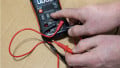
Voltage is easily measured with a voltmeter, since such a connection is a high-impedance parallel connection between the meter leads and the load wires. Current-carrying wires, on the other hand, require an extremely sensitive Hall effect non-contact sensor, or the circuit must be broken while an in-line current meter is connected. Obviously, breaking the circuit is less than ideal for a running operation.
Which is Better, Voltage or Current?
As with many industrial standard debates, I cannot provide input on which is superior to the other. The best was can say is that for either system, there can be tremendous advantages, so it is best to have a thorough understanding of how to install, troubleshoot, and design around either one.
Although they both exist, the 4-20 mA standard is more common for sensing devices in automation. If your experience involves only voltage signals, it would be beneficial to invest time in investigating the current signal standard. With the right design choices, you have the ability to engineer the best system possible to balance signal reliability with ease of troubleshooting to design a resilient, future-proof control system.