 Facebook
 Google
 GitHub
 Linkedin
Why is 4-20 mA Current Used for Industrial Analog Sensors?
Industrial analog sensor devices primarily use 0-10 volt or 4-20 milliamp. For those mA signals, learn the reasons for why the lower and upper limit standards were determined as 4 mA and 20 mA.
Before electrical control systems were prevalent, pneumatic control systems were used. The controllers in pneumatic systems were powered by varying the pressure of compressed air in the range of 3-15 psi. The lower end was set at 3 psi as it is difficult to build systems that can detect pressure below 3 psi. When electrical control systems became popular, current signals in the 4-20 mA range became the popular choice.
In this article, you will get to know why current signals are chosen over voltage signals. We will also discuss the rationale for selecting current signals in the 4-20 mA range.
Current Signal: More Reliable than Voltage Signal
Current signals and voltage signals can be used to transmit electrical signals, but in most instrumentation applications, current signals are used instead of voltage. One of the reasons for this is the voltage drop that happens when signals are transmitted over long distances. Constant current outputs simply increase the driving voltage to compensate for line losses, thus they do not experience such a degradation, making them better suited to transmit electrical signals. Strong current signals can be easily transmitted over wires with lengths up to 1 kilometer.
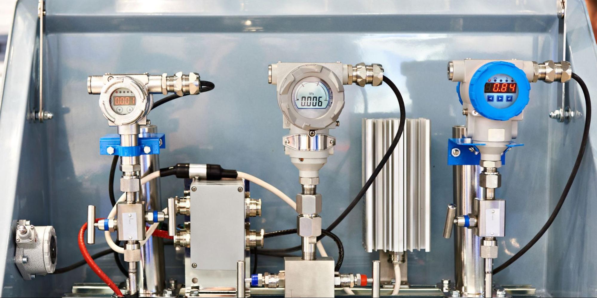
Figure 1. Pressure and flow measurements are usually analog signals, many times following the 4-20 mA standard. Image used courtesy of Canva
Current signals have a much more linear response compared to voltage signals. This makes calibration easier with current signals. Current signals are also immune to noise by providing a low impedance for the sensors. For these reasons, current signals are preferred over voltage signals for transmitting electrical signals.
The 4-20 mA Current Range
Transmitters used in automation applications can output signals in two ranges.
1. 0-20 mA range: Here, 0 mA represents 0% of the measured process variable. 20 mA represents 100% of the measured process variable.
2. 4-20 mA range: Here, 4 mA represents 0% of the measured process variable. 20 mA represents 100% of the measured process variable.
The 4-20 mA range is the preferred choice for signal transmission. The span of the signal is 16 mA.
$$Span = High~Value - Low~Value$$
$$Span = 20~mA~-~4~mA$$
$$Span = 16~mA$$
$$Variable = \frac {Actual~Val - Low~Val}{Span} \times 100\%$$
|
Current Signal Value |
Process Variable |
|
4 |
0 |
|
8 |
25 |
|
12 |
50 |
|
16 |
75 |
|
20 |
100 |
The lower range is selected as 4 mA and the upper range is selected as 20 mA due—these reasons will be discussed in the following sections.
Dead Zero Problem
Consider a sensor measuring the temperature of an object within the range 20° C to 100° C. The transmitter can send signals in the 0-20 mA range or 4-20 mA range.
If the transmitter sends signals in the 0-20 mA range, a 20 mA signal at the PLC represents 100 °C. The transmitter sends a 0 mA signal to the PLC when the temperature is 20 °C. The temperature transmitter loop could experience faults. The fault could be due to a broken wire, faulty transmitter, high wire resistance, noise, or other problems. When such a fault is present in the temperature transmitter loop, the PLC receives a 0 mA input. Even if the real temperature is 40 °C, the PLC receives 0 mA as input. Due to this, the measurement is recorded as 20 °C instead of the real 40 °C temperature.
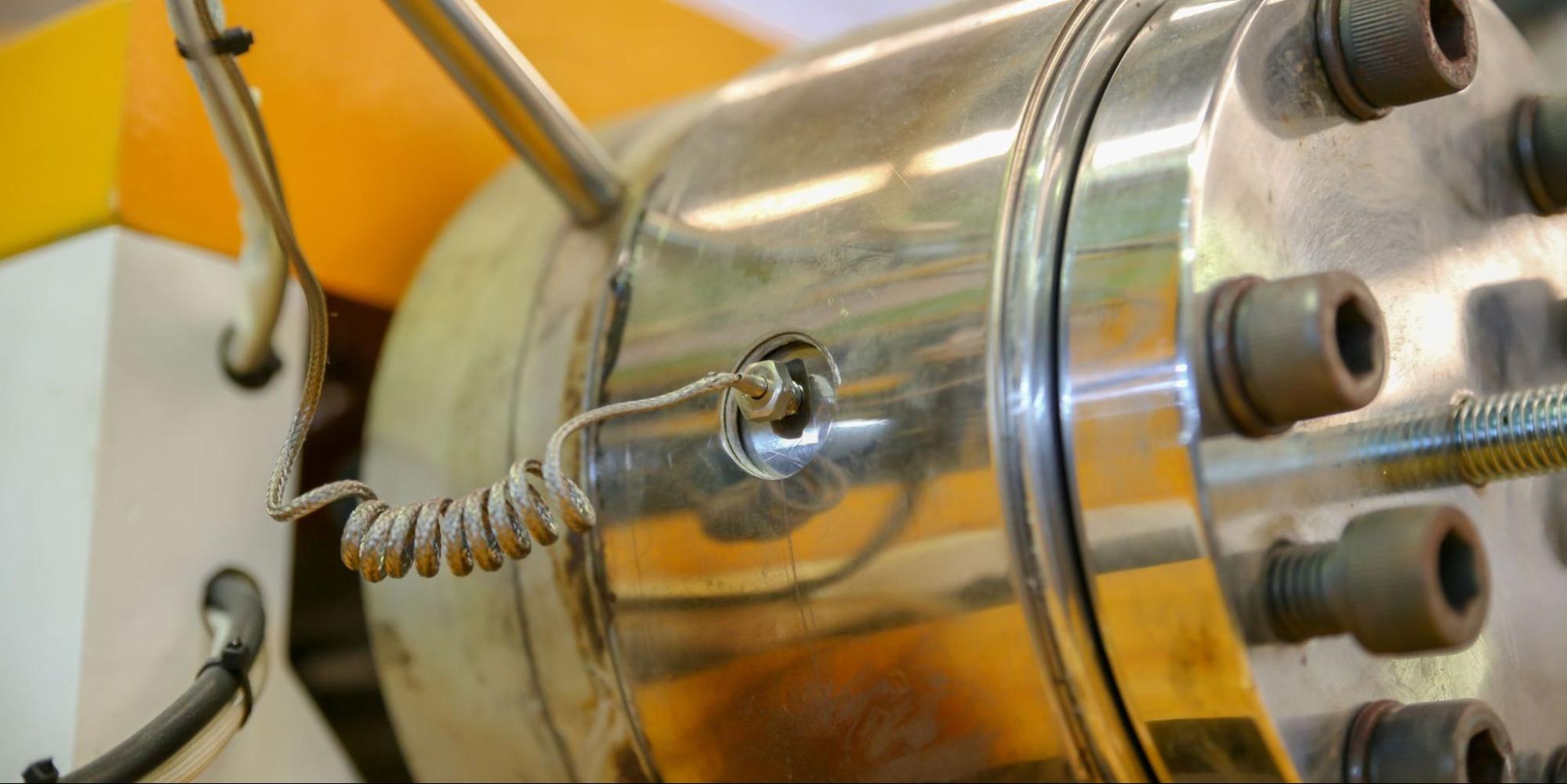
Figure 2. Temperature measurement, in the form of thermocouples, are critical analog process measurements. Image used courtesy of Canva
This is the dead zero problem. The PLC cannot distinguish between a faulty transmitter loop and the lower range of the measured process variable. Considering that PLCs of the past did not have features like diagnostic circuits and fault identification, the dead zero problem was a big challenge.
The dead zero problem can be eliminated by having an elevated live zero. Elevated live zero means the lower range of the measured value will be represented by a current signal of more than 0 mA. When the 4-20 mA transmitter signal range is used, 4 mA represents the lower range. In the previous example, 4 mA will indicate 20 °C. When there is a fault in the transmitter loop, the PLC receives 0 mA as the input. Since it does not represent any measured value, it can be identified as a fault.
Loop-Powered Instruments
Any current above 0 mA can be chosen to represent the lower range of the measured process variable to eliminate the dead zero problem. But why 4 mA is chosen as the elevated live zero is due to other reasons.
When loop-powered field instruments are not used, the field instruments have to be 3 or 4 wire units. This increases installation costs. When the instruments can be powered by current in the transmitter loop, the installation and configuration of field instruments becomes simple.
The power consumption of analogous devices used to be pretty high. Analog transmitters require a minimum of 3 mA of current to operate. Due to this, the lower range has to be more than the 3 mA required to power the transmitter loop, and 4 mA current was taken as the reference considering a margin for errors.
Why the 20 mA Upper Limit?
30 mA current was considered a dangerous threshold for the human heart. So for safety reasons, a value less than 30 mA had to be used for the upper range, with 20 mA as the choice.

Figure 3. Current is not only necessary for signals, but is also a key performance metric for machine and human safety. Image used courtesy of Canva
Transition Considerations
Industry was using pneumatic controllers with the range 3-15 psi, which was an industry standard. The ratio of the lower range to the upper range is 1:5. The analog equipment to replace these pneumatic devices has to handle 3-15 psi signals. The design engineers used the same ratio (1:5) for the current signals. This helped engineers design equipment with better linearity and accuracy, thus facilitating easy calculations. This eventually led to choosing the 4-20 mA current range, which has a ratio of 1:5 between the lower range and the upper range.
Analog to Digital Conversion (ADC)
Some controller CPUs require digital signals in the range 1-5 V. To convert 4-20 mA current to a 1-5 V digital signal, a simple 250 Ω precision resistor would do the job.
According to Ohm’s law:
$$V = I \times R$$
|
Current (in mA) |
Resistance (in Ω) |
Voltage (in V) |
|
4 |
250 |
1 |
|
8 |
250 |
2 |
|
12 |
250 |
3 |
|
16 |
250 |
4 |
|
20 |
250 |
5 |
Ease of this conversion also favored the use of the 4-20 mA current signal.
Analog Current Signal Summary
Due to multiple reasons, the 4-20 mA current signals have become the industry standard for automation. This choice became predominant due to some of its benefits:
-
Easy installation and configuration
-
Simple multimeters can be used for troubleshooting, eliminating the need for specialized equipment
-
Easy fault detection using elevated live zero
-
Least susceptible to external noise
The use of 4-20 mA signals could introduce magnetic fields and crosstalk in parallel cables. Take the precaution to use twisted pair cables to cancel out the magnetic fields induced. Also keep in mind that each pair of cables can carry only one process variable.
Related Content


Several other reasons for the wide spread use of 4-20mA as a process signal:
1. ‘Smart’ transmitters can, in many cases, signal a fault condition with 4-20mA; typically a high value at 21.5mA or a low value at 3.6mA
2. 4-20mA being essentially DC signal, can operate with a superimposed, higher audio frequency signal, HART, for digital communications. HART is primarily used for configuration and troubleshooting, but can be used for low throughput data communications.
3. 4-20mA can be designed and approved as Intrinsically Safe
4. The mentioned 1 km distance can be extended to several kilometers with either a larger conductor size or higher loop DC voltage power supply.
5. An accidental or deliberate electrical short on the output of a 4-20mA analog output does not damage the 4-20mA circuit because 4-20mA is a regulated output.
6. Even a cheap $10 DVM can be used to troubleshoot a 4-20mA circuit.
7. As a current signal, it offers a wide choice of dropping or shunt resistors on analog inputs for conversion to a voltage signal. Although 250 Ohms is common, values from 1 Ohm to 500 Ohms are encountered.
8. Depending on ground potentials, 4-20mA can drive two devices’ analog inputs in series, as long as the total resistance load can be driven by the available loop voltage.
9. 4-20mA analog output offers enough ‘power’ to drive many models of analog or smart valve positioners.
Nice article. As an “old analog guy” I started in the process control industry in the 1960s. I worked for Taylor Instruments (no longer in business under that name) and remember 1-5mA, 4-20mA and 10-50mA (I think the latter was European - not sure). We offered all three as options. In those days, half our instruments were pneumatic, 3-15 psi, amazing precision from that mechanical stuff. I didn’t design those - only electronics. 1mA would be too small for loop-powered instruments. I wasn’t aware of the safety concerns over 30mA - learned that from your article.
A senior engineer I worked under told me once worked on a project to design their first transistorized milllivolt transmitter. They did have products using chopper-stabilized vacuum tube amplifiers. He said he met the performance and cost goals but, in a management-level review, was told, “No - too many transistors!”