 Facebook
 Google
 GitHub
 Linkedin
Inrush Current: Why Is Motor Startup Current So High?
Motors consume the highest current during startup—this is a well-known fact. But logically, the slowest speed should relate to the lowest power consumption. Why, then, is inrush current so high for motors?
Motor current monitoring is a common practice. Using either handheld clamp meters or fixed power level and quality analyzers, it is generally well-known to most engineers and technicians that motors will consume more current at startup.
This phenomenon is no minor difference. It can sometimes be as much as 10x to 20x higher current consumed for a brief moment while the motor is gaining speed.
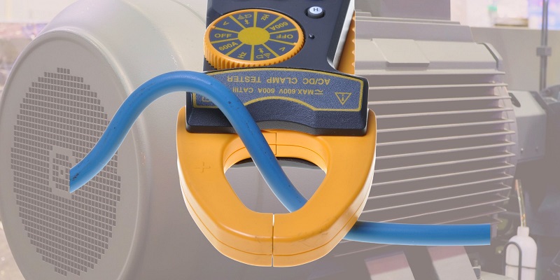
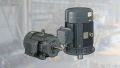
Figure 1. Current is measured with clamp meters, and motors display very high startup current.
Why Is Motor Inrush Current So High?
Although commonly understood, this fact seems counterintuitive to common sense: slower motion (less work done over time) consumes less energy and, therefore, lower power. Lower power on a fixed voltage source should equal lower current consumption. Even the common formula relating torque, power, and RPM states:
$$ Power = Torque (\tau) \times RPM $$
This equation also seems to correlate a low RPM to low power consumption.
Using these foundational physics equations, it seems difficult to justify the obviously measurable reality of why inrush current is so high.
Motor Coil Impedance
In any motor, one part moves while the other stays stationary. In most motors, this means that the central shaft is the rotor (rotating) while the outer casing stays stationary (stator). Not so in many brushless motors where the outside rotates; however, this article will mainly address induction motors.
The coils that make up the windings in the stator are wound around ferrous poles. This creates an RL circuit with some resistance of the wire itself and the natural induction formed by the coils. The moment voltage is applied to the leads, the magnetic field acts on the ferrous metal and provides reactance (which resists current flow).
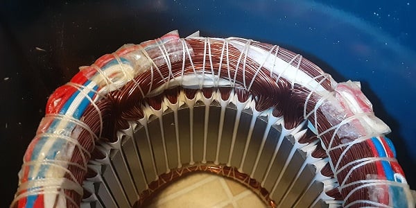
Figure 2. Three-phase motor with stator windings around iron poles.
Here, I have a motor wired for a three-phase 480 V input, with 16.5 Ω of resistance measured between T leads. The FLA (amps) rating for this ¾ HP motor is 1.5 A at 480 V. This equates to a total impedance of 320 Ω, substantially more than the 16.5 Ω of resistance of the coils alone.
This extra resistance is due to the inductive reactance of the motor, both from the stator and the rotor.
How do we know this? If the impedance were due to the stator’s windings and poles alone, there would be no difference between a stopped versus running motor. As the motor picks up speed, the resistance (and reactance) increases so that the current inversely decreases.
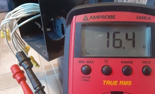
Figure 3. Measured resistance of motor windings between T-leads, configured for 480 V.
Reverse Voltage, or Back EMF
When the motor runs at full speed, a load is placed on the inductor, causing it to expend energy to reverse the polarity in the laminated layers of the rotor core. In other words, it must consume far more energy to both rotate the shaft and polarize the metal at the same time.
The loading effect can also be demonstrated with a small DC motor: rotate the shaft while keeping the lead wires disconnected (no load), and it will spin easily. Connect a light bulb or resistor across the leads, and spinning the shaft becomes more difficult. When a magnetic field generates energy to be converted into light, heat, or motion, it causes tremendous resistance.
In an induction motor, this back EMF (electro-motive force, or voltage) provides enough resistance to drop the current from an incredibly high startup value to the nominal ‘full load’ amps at full speed.
Another common analogy is observing the effect of a transformer under no-load and full-load conditions. When no load is connected, little effort is needed to polarize the iron core, and the supply current will be high. When a variable load is connected and slowly increased, the load current drops, and so does the supply current.
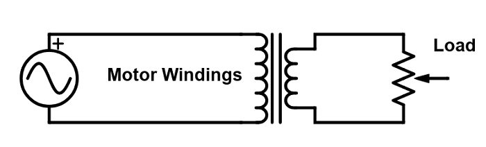
Figure 4. Transformer analogy of motor loading effects.
First Question: Should an Unloaded Motor Have Higher Current?
If it’s true that the increasing load increases the back EMF, then should a free-spinning motor with load disconnected have a much higher current and probably blow the supply fuses and breakers?
When energy is consumed to move a load, this is called power. If a motor is unloaded, the power generated is quite small. There is certainly back EMF from the rotor, but the power requirement of the motor is much lower. Since power equals:
\[Voltage \times Current \]
...and the voltage supply from the mains stays relatively the same, the current will be lower.
So, the current is lowered in an unloaded motor because the power demanded and generated by the motor is lower. The current is lowered in a loaded motor because of the back EMF asserted by the heavier load.
Of those two situations, however, it will usually be the case that an unloaded motor will consume less current than the same motor under load.
Second Question: Is the High Current Due to Acceleration or Simply RPM?
In a physical kinematics course, the go-to equation says that:
\[Force = Mass \times Acceleration\]
...or...
\[F = M \times A\]
If there is no acceleration (or constant motion), no additional force is required, and therefore power should be minimized. So, if the motor is stopped, there should be very little current. Only the brief moment while the motor accelerates will be the high inrush current period.
However, any electrician who has dealt with stalled motor (or locked rotor) current knows that a stopped motor can still consume massive current and cause faults. This proves that, while acceleration requires more power and will increase the current, the rotor's speed, not the acceleration, must have a powerful impact on the current consumption.
Motor Current Faults
Most of the time, this high startup current is expected and normal. Many motor starter devices have breaker curves that allow high current for short periods of time, spending on both the motor and the load situation.
Correcting failed motors is a time-consuming and expensive process. Understanding how, when, and why these high current situations occur can help to reduce the costs and hazards of these common problems.
Interested in more content about motors? We have plenty to choose from!
Articles:
- Comparing Single-Phase and Three-Phase Motors
- 3-phase Motor Types: Synchronous and Induction Motors
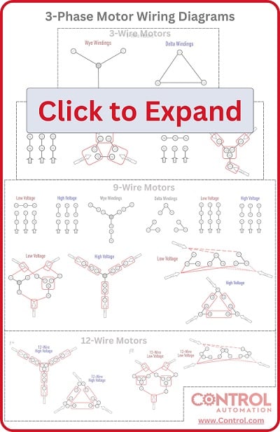
- Understanding Delta Wound Motors for Industrial Applications
- Brushed vs. Brushless DC Motors
- Field-oriented Control (Vector Control) for Brushless DC Motors
- Teardown: What’s Inside a 3-Phase Induction Motor?
Textbook:


Motor inrush is a function of motor design not load. A motor is a transformer and at start-up it is a transformer with a shorted secondary. In other words, a short circuit; hence high inrush. The inrush is the same whether the motor is loaded or unloaded, although the duration may be different. As the inductor sees current flow it magnetizes the stator and becomes a “choke” which limits the current.
Here’s a simple way of looking at it on a DC motor.
Electrically at low frequencies where stray inductance doesn’t count the motor behaves like a capacitor.
It stores energy as angular momentum, not charge but the principle holds. Current accelerates the motor, adding to its momentum.
The motor’s back emf is a function of its rotation speed.
When you first apply voltage you need to “charge up” the motor’s momentum, which takes significant energy.