Facebook
 Google
 GitHub
 Linkedin
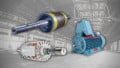
Teardown: What’s Inside a 3-Phase Induction Motor?
Coil, field winding, rotor, stator, eddy current… When it comes to motors, there are numerous terms that describe the theory of operation, but what is inside a 3-phase motor? Take a look, and learn how they work.
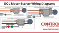
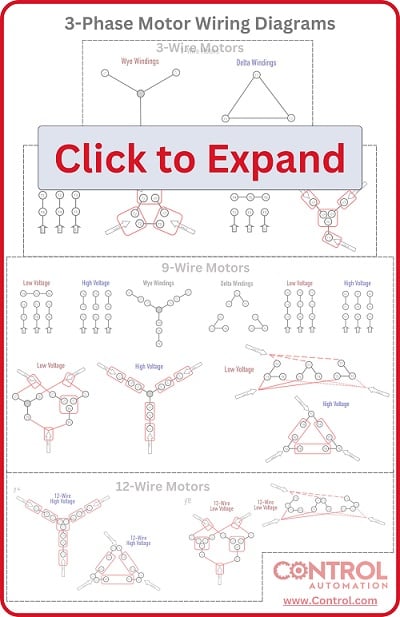
Check out Control Automation's exclusive eBook on motor wiring

One of the most common devices to find inside any industrial operation is the 3-phase induction motor. These can range from small, fractional horsepower (HP) devices to gigantic multi-thousand HP motors requiring hundreds of amps with kilovolt supplies. When it comes to motors, whether AC or DC, the theory of electrically-driven magnetic fields propels the world of motion.
We disassembled a small, 1-HP motor to explore the components in the assembly and learn how to care for these devices and keep them running for many years of reliable service.
Are you a motor troubleshooting expert? Quiz yourself with our (no pressure) worksheet!
The Outer Casing
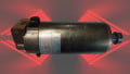
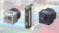
The most visible part of the motor is the outer metal casing. For these 3-phase induction motors, there are likely to be a few similarities. First, a sealed wiring box extends out the side. These can contain 3, 6, 9, or 12 wires, with 9 being the most common variation. Weather-resistant gaskets prevent moisture from corroding the wire nuts or screw terminals inside this wiring box.
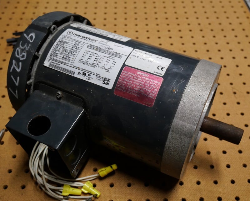
Figure 1. Today’s unwilling participant: a 1-HP 3-phase motor.
The data plate on the side of the motor explains the details of proper wiring and the electrical properties which are important both for installation and for setting parameters on a digital drive (VFD).
Motor Cooling Fan
There are many models of motor housing for various environmental situations. General purpose, severe-duty, washdown tolerant, food grade, etc. are just a few examples that can change exactly how a motor is constructed.
For this general-purpose situation, it is common to find a fan attached to the drive shaft on the reverse end of the motor, covered by a shroud to protect the blades and operators from damage.

Figure 2. Cooling fan with the shroud removed. Note the moisture corrosion on the retaining clip, indicated by its green color.
This fan is usually constructed from plastic to reduce weight and is carefully balanced so that it will not introduce vibration to the motor. In cases of extreme heat or damage, the fan can twist, warp, or break, so it is important to be very careful to keep the casing free from obstructions or conditions that are out of tolerance for the motor model.
Removing the End Caps
For most smaller motors, a set of long screws secures the front end to the back end, containing the entire assembly together in the middle of the motor case.

Figure 3. Long screws attach the front end of the casing to the back end.
Once these screws are removed, both ends can be removed with little force. If you ever must perform this level of disassembly, there are a few important details to explain.
The inner part of the induction motor is the part that actually rotates, and this contains the shaft of the motor, into which the entire external machinery depends. This rotating component is called the ‘rotor’. You can see the end of the rotor extending from the body of the motor in Figure 4 below.

Figure 4. With the end plate removed, the shaft of the rotor is clearly visible. This is the reverse side of the motor, so this is where the fan was installed before it was removed.
The motion of the rotor is perhaps the most important quality of the motor, aside from the electromagnetic coils themselves. A roller bearing is carefully selected and installed to ensure the shaft rotates concentrically through the coils. A wave washer, along with grease, is installed to be sure that once the screws are tightened, the end cover never comes in contact with the moving race of the bearing. If this were to happen, friction would increase, causing heat, damage, and eventual failure. Take note of any washers that should be included with the reassembly. If missed, you may not notice the problem immediately, but you can expect the lifespan will be shortened.
Front-end Cover
The front end of the motor is removed with a gentle application of force. In this case, it came out with the front motor bearing still firmly press-fit in place.
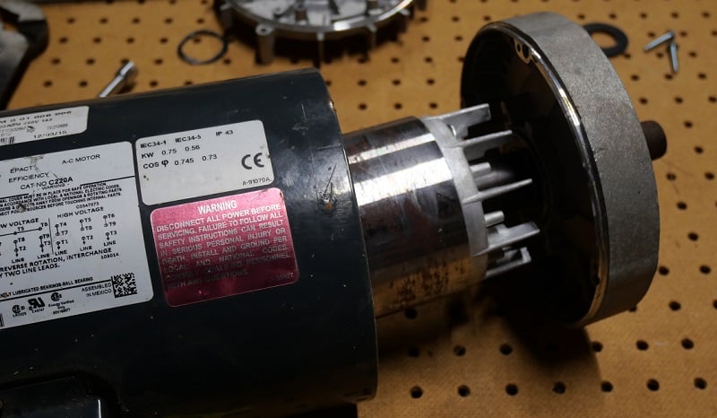
Figure 5. The front end of the motor with the rotor still attached.
The rotor itself is never attached to either the front or back cover. If it were, it would be unable to spin freely. The goal of the motor design is to construct it with zero vibration (meaning a very tight tolerance bearing) with zero friction (meaning not TOO tight on the bearing). That means the rotor can be removed from both end plates with just a gentle application of force.
Do not ever try to remove the rotor bearings by hitting it with a steel hammer, unless you hit in a perfectly axial direction (not from the side of the shaft)—you should not need to hit it hard. Many motor shafts have been bent or have bearings damaged by over-enthusiastic removal attempts.
The Rotor
The rotating piece in the center of the motor is one half of the interaction that actually makes a motor work. We’ll get to the winding coils in just a minute.
The rotor is a carefully constructed, perfectly balanced shaft of metal with a high iron concentration. This ferrous content allows it to be influenced by the current in the coils around it. As the current progressively charges the winding coils, the rotor responds with a magnetic attraction in incremental degrees around the outside, pushing and pulling it in a circle. Smooth balanced rotation.

Figure 6. The motor’s rotating component, the ‘rotor’.
I want you to look carefully at a close-up view of the rotor construction and observe a very important quality about it.

Figure 7. Close-up of the rotor construction.
The rotor appears to be made out of hundreds of thin slices of metal, all bonded together. In fact, this is exactly what it is. This is referred to as a ‘laminated’ construction, with each iron layer separated by an electrically insulated disk. The reason for this construction is a concept called an ‘eddy current’.
What is Eddy Current?
When the winding coil generates a magnetic field, it will polarize any ferrous metal nearby, giving it a magnetic attraction. This causes the motor to spin.
However, that same magnetic field will also attempt to cause a current to flow. The current will attempt to flow around the rotor itself. Now, not only is the rotor spinning, it is also conducting electricity as a circuit. This generates heat, causes inefficiency, and is undesirable for a motor.
By slicing the metal disks into individual, isolated sections, the current is stopped and the risk of eddy currents is removed.
If you ever see the construction of an iron-core transformer, you will notice the same laminated construction. In a transformer, we want the secondary coil to generate an electric current—we definitely don’t want to see any current traveling through the core.
The Winding Coils in the Stator
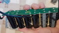
Finally, the last important piece of the motor is the set of windings wrapped around the rotor but never contacting it. Since this part of the motor is stationary, it is called the ‘stator’, to complement the rotor.
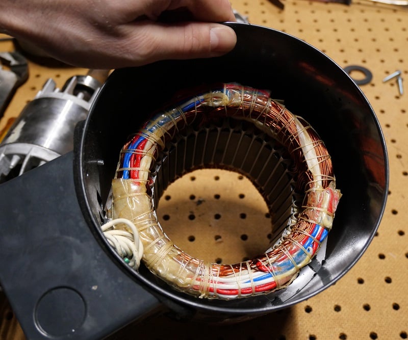
Figure 8. The winding coils.
The 3 phases of electricity are not placed in three groups around the outside edge, as might be often shown in simple animated graphics of motor theory. If there were only 3 large windings, the force would be applied only to one edge of the rotor at a time—not very good for balanced rotation.
Instead, the three phases are split and distributed around the perimeter, providing a nice, smooth balance of force.

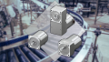
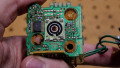
Figure 9. Close-up of the stator, with the windings passing through isolated slots.
This motor has 36 individual winding distributions. This means that each phase will be energized equally 12x times around the perimeter, as distributed by the 6 individual coils, and wired for high or low voltage by the electrician.
3-Phase Motor Construction
Motors are one of the oldest categories of electric devices. But this should not be interpreted to mean they are obsolete or outdated by any means. Motors are a continual source of troubleshooting and maintenance, and understanding the construction and theory can provide excellent insight into keeping them in service for a very long time.
Interested in more content about motors? We have plenty to choose from!
Articles:
- Comparing Single-Phase and Three-Phase Motors
- 3-phase Motor Types: Synchronous and Induction Motors
- Understanding Delta Wound Motors for Industrial Applications
- Brushed vs. Brushless DC Motors
- Field-oriented Control (Vector Control) for Brushless DC Motors
Textbook: