Facebook
 Google
 GitHub
 Linkedin
Common Motor Windings and Wiring for Three-Phase Motors
This article looks at some common windings and wirings for three-phase motors, including internal Wye windings and low and high voltage wirings.
Check out Control Automation's exclusive eBook on motor wiring

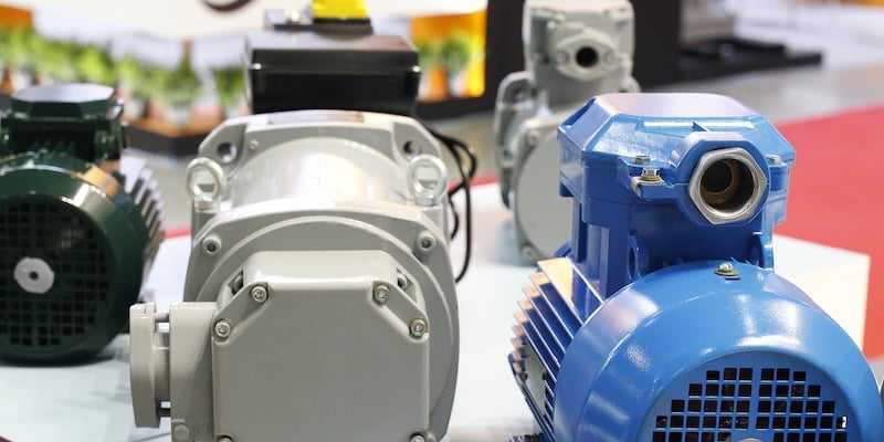
Three-phase motors will almost always have a bundle of wires coming out the side, meant for connections to both incoming line power as well as establishing connections between windings. However, there is much more behind the scenes than simply connecting wires.
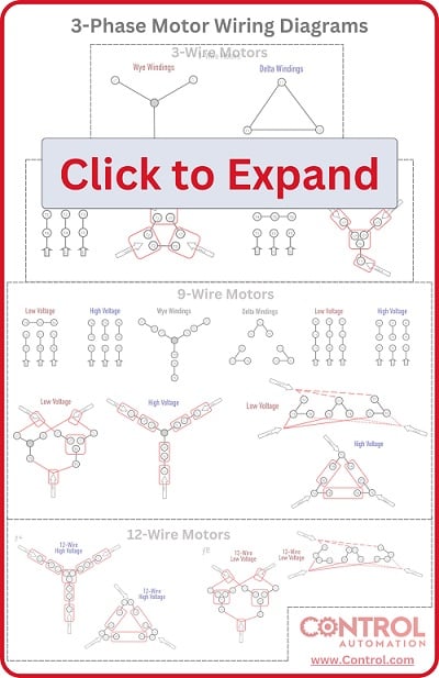
Most of these motors have 9 lead wires, designed to produce just the right amount of magnetic power from a high or low-voltage source. Plus, some motors have wye (star) or delta internal wiring. The connection diagram may be the same on the outside, but illustrating the wiring style can help visualize how those windings are arranged to convert just the right amount of power into a rotating magnetic field.
There is a wide variety that exists in the manufacturing of three-phase motors that drive heavy industrial loads. It would not be correct to say that one type of motor is superior, otherwise, that’s the only kind of motor that would exist. Instead, we see a few different motor types, often indicated by the wires and the data plate on the side.
The variety of motors is typically most obvious in the number of wires requiring connections. For the electrician, nothing is more important than understanding which wires should be connected to the incoming voltage lines for proper operation.
Are you a motor troubleshooting expert? Quiz yourself with our (no pressure) worksheet!
Nine-Wire Three-Phase Motors
The most common type of three-phase motor is that which has nine labeled (and often colored) wires coming out of the box on the side. There are many motors with more or fewer wires, but nine is the most common.
These nine-wire motors may be internally connected with either a Wye (star) or a Delta configuration, established by the manufacturer. Both have different purposes, but fortunately, they can usually be used interchangeably.
Regardless of the internal type of wiring, these motors can be connected to either a Wye or Delta supply - the supply and the motor are two entirely different subjects.
However, if a motor is wired for low voltage, do not EVER connect it to a high voltage source (either Wye or Delta) as it will overheat. On the other hand, if a motor is wired for high voltage, it will fail to operate if connected to a low-voltage source.
Motor Connections in Wye (Star)
For those standard nine-wire motors that have internal Wye (or star) connections from the factory, a mental image of the winding arrangement may provide some insight for the reason behind making certain connections.
If you need to see a delta wiring connection, see our additional article.
For these motors, there will be an indicator on the data plate of two different wiring scenarios - one for low voltage (208-240) and another for high voltage (480).
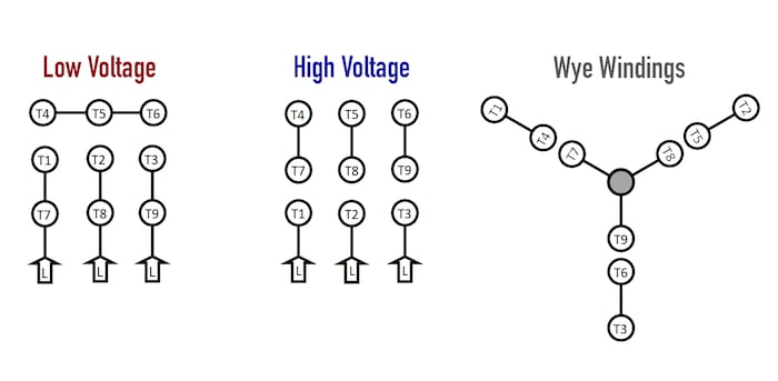
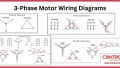
Figure 1. The internal arrangement of a Wye-wound three-phase motor with nine leads. Those nine leads provide an option for supplying power from either high or low voltage sources.
For the low voltage option, the instructions show to connect the following:
T4-T5-T6, T1-T7-Line, T2-T8-Line, and finally T3-T9-Line.
For high voltage, the wiring changes:
T4-T7, T5-T8, T6-T9, T1-Line, T2-Line, and T3-Line.
Internally, there are 6 distinct wound coils, distributed equally around the outside of the rotor. The main purpose of this distribution is to ensure that the coils on opposite sides of the rotor are energized equally at any time for a balanced application of force.
With a lower source voltage, those two opposite windings must be in parallel to receive the proper voltage simultaneously. For high voltage, the opposite windings in series will yield the proper voltage at the same moment.
Low Voltage Wiring
When the supply voltage is lower, the total resistance of the load must also be lower in order to generate the same output power. As long as the resistance stays equal, then an equal application of voltage should then also yield an equal output power for each winding. According to Watt’s Law:
Power = Voltage2 / Resistance
Since the voltage is squared, doubling that voltage from a low (240) to a high (480) source would require a 4x increase in resistance to maintain an equal output power.
In order to achieve this lower resistance, the ideal configuration would be a parallel network. This is accomplished by creating a second small bonded Wye set of coils in the motor. Both of these small parallel Wye’s will be supplied with an incoming line lead.
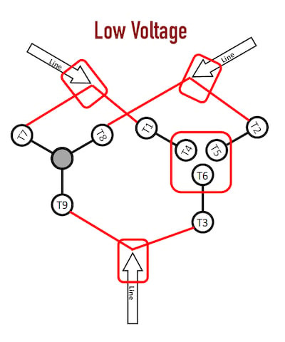
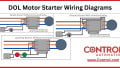
Figure 2. The connections required for low-voltage wiring of a wye-wound motor.
This image shows the representation of those two small Wye shapes by first bonding T leads 4-5-6, then by connecting T4 and T7 to a Line, as well as T5 and T8, then T6 and T9 each to Line leads as well.
Imagine from Line 1 (top-left) to Line 2 (top-right). The current may travel from Line 1, through T7, to T8 back to Line 2. In parallel, it may travel from Line 1, through T1, T4/T5, then T2 back to Line. Both parallel paths contain two series windings. The total resistance, therefore, will be equal to the resistance of 1 winding alone.
For a 240-volt input, each of the windings will drop 120 volts, since there are two windings in series in each path.
High Voltage Wiring
For high voltage, the total resistance must be 4x higher than for low voltage in order to maintain the rated output power.
The image representation of this wiring scheme is easier to visualize. The original wiring diagram showed the proper arrangement of windings to create a larger Wye system in which there are four equal windings between any two leads.
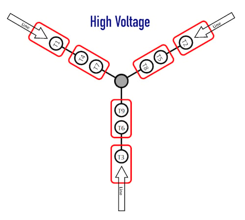
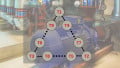
Figure 3. The connections required for high-voltage wiring of a wye-wound motor.
In this wiring setup, there are 4 windings in series between any two Line leads. Compare this to the low voltage. From Line 1 (top-left) to Line 2 (top-right), the current only has one path through T1, T4, T7, T8, T5, and T2 back to Line. This gives a resistance equal to 4x the value of one single winding.
Again, comparing the power to the low voltage, if the input voltage is 480 volts, each of the 4 series windings will drop 120 volts. This is the same voltage, and therefore the same power, as the low voltage scheme.
Interested in more content about motors? We have plenty to choose from!
Articles:
- Comparing Single-Phase and Three-Phase Motors
- 3-phase Motor Types: Synchronous and Induction Motors
- Understanding Delta Wound Motors for Industrial Applications
- Brushed vs. Brushless DC Motors
- Field-oriented Control (Vector Control) for Brushless DC Motors
- Teardown: What’s Inside a 3-Phase Induction Motor?
Textbook: