Facebook
 Google
 GitHub
 Linkedin
How to Wire Motor Starters and Contactors
This article investigates the basic components and wiring conventions for common three-phase motor starter configurations, including direct online, reversing, and star-delta.
Motor starters are necessary for the proper operation of most industrial AC motors, whether they consist of a single phase or three phases. Electrical motors produce a large current draw upon startup, often many times larger than the current draw expected from the motors during normal operation. Motor starters provide the components necessary to both control and protect motor circuits.
Ensure that you understand the motor before wiring the starter. Read the installation instructions first. Identify the leads, match the incoming phase leads to the input terminals on the starter, then connect the outgoing motor leads to the output terminals on the starter.
Basic Components of a Motor Starter
Motor starters generally consist of two main components: a contactor and an overload relay. The contactor is the heavy-duty switch used to supply the motor power whenever it is needed. An overload relay is usually incorporated in series with the contactor coil to stop the flow of power in the case of overcurrent or low-voltage situations. The overload relay can be adjusted to fit the size of the motor and the current that it is expected to draw, giving more flexibility to the motor starter.

Figure 1. Wiring motor starters can be a tricky business with so many power and control configurations. Image used courtesy of Adobe Stock
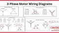
Three-Phase Motor Starters
Three-phase motor starters can be wired in different configurations depending on the intended use of the motor and the design of the circuit, but the basic principles are the same for all motor starters.
Are you a motor troubleshooting expert? Quiz yourself with our (no pressure) worksheet!
Most motor starters consist of the contactor, an overload relay, and some type of manual or automated control circuit. The control is most likely either 120 VAC or 24 VDC, but sometimes up to 230 VAC and over 100 VDC.
Motor Starter Wiring Diagram
One of the most common types of motor starters is a direct online or DOL, motor starter. They are often used on smaller motors because they switch 100% of the power to the motor on start-up, creating a large current draw. For large motors, contactors may be used, but soft starts, VFDs, and reduced voltage starters have become increasingly common.
Direct Online Starter Without Reverse
A DOL starter without reverse functionality is the simplest type of motor starter, so we will discuss this wiring convention first.
Wiring Incoming Power to Contactor
Three-phase power has three legs: L1, L2, and L3. These will be wired directly to the top of the starter contactor into terminals 1/L1, 3/L2, and 5/L3. Usually, the incoming motor power connection is quite straightforward.
Wiring Contactor to Overload (OL) Relay
The overload is usually directly connected directly onto the outgoing contacts of the main contactor body with prongs that can simply be tightened down with a torque screwdriver; these are often labeled as 2/T1, 4/T2, 6/T3, as they supply the T leads for the motor itself.
Wiring Overload to Motor Leads
The outgoing terminals of the (optional) overload should have the same labels as the contactor itself: 2/T1, 4/T2, 6/T3, or similar. The wires for powering the motor should be connected directly to these ports.
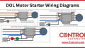
To summarize this wiring scheme, phase 1 passes out to the motor through terminal 2/T1, phase 2 exits through terminal 4/T2, and phase 3 through terminal 6/T3.

Figure 2. Click to see an expanded version of the various methods of wiring a DOL motor starter.
Wiring The Control Circuit (Coil)
The control circuit (coil) needs to be wired to either an ON/OFF push button circuit or the DC/relay outputs of a PLC; contactors are never analog devices. The coil accepts the input signal to start the motor whenever necessary. In our example, we have used a 24 VDC control voltage.
Using a PLC or Electromechanical Switch
When using a PLC, the output can be directly connected to coil terminal A1, with terminal A2 continuing to the 0 VDC rail or the overload relay (explained below). The PLC can handle any latching or timing functions, so the wiring is very simple.
When using a manual pushbutton switch, most contactors provide additional terminals to aid in various circuits. A stop and start button are wired in series from 24 VDC, and then the NO auxiliary contacts (terminals 13/14 or 53/54) are connected in parallel with the start button to provide an on/off latch. This start button is then connected to the A1 coil terminal, with A2 returning to 0 VDC.
If an overload relay is provided, the A2 coil terminal is connected to the OL relay NC contact 95, and then terminal 96 returns to 0 VDC. This NC contact opens the circuit in case of dangerous overcurrent.
DOL Reversing Motor Starter
DOL starters with reversing capabilities are very similar to standard DOL starters. The wiring terminals are the same, with the exception that DOL with reverse uses two contactors. The extra contactor will provide the motor with reverse by switching two of the legs, effectively making the motor start in the opposite direction.
Both contactors will be wired the same, and each will require individual interlocked buttons, with one labeled forward and one reverse. When using a PLC, an extra +24VDC output will be used to supply the second coil with power from a PLC, never energized at the same time.
A mechanical or relay interlock is employed to ensure that both contactors can never be energized at the same time, while a second relay may provide on/off control, as shown below in Figure 3. If a PLC is used, simple logic may allow on/off and fwd/rev control.
The three legs of the contactors will be wired together, meaning the L1, L2, and L3 will still be the incoming power, but the terminal 1/L1 of the first contactor will connect to 3/L2 of the second. Likewise, 3/L2 will connect to 1/L1. All terminals on the other side of the contactors will be jumpered together before entering the overload. Sometimes, reversing bus bars are used, which also reverse L1 and L2 for the incoming power. Any two lines can be reversed, but for consistency, this is a common convention.

Figure 3. Wiring diagram for a simple reversing starter circuit with a relay for Start/Stop and a relay for Fwd/Rev control.
Star-Delta Starter
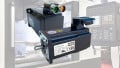
Star-delta (or wye-delta) starters are used to reduce the current draw of a three-phase motor on startup, they do this by first starting the motor in a high-resistance star configuration and then switching to a low-resistance delta configuration once the motor is up to a higher speed. They generally consist of either three contactors or one 3-pole double-throw relay and a 3-pole contactor (for small motors).
The wiring for this type of configuration is slightly more complex since the wiring of the motor itself must be considered, in addition to the wiring of the starter device.
To read a more in-depth explanation of the wiring arrangement in a star-delta circuit, see our technical article that explains both the theory of the motor wiring and the control circuit diagram.
Wiring Starters
With multiple coils, main contacts, and various control peripherals, it’s no surprise that wiring starters can be difficult. Consult local guides before connecting any motors, but take the time to understand various circuits, and it will be much easier to predict problems and solve errors in the future.