Facebook
 Google
 GitHub
 Linkedin
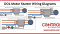
Star-Delta Wiring for Reduced Voltage Starting of 3-Phase Motors
Digital controls like VFDs and soft starts have advantages by elongating start time, but simple strategies for starting motors with a reduced current draw, like star-delta (or wye-delta) are common.
The heaviest burden for a 3-phase motor control circuit is the moment of startup when the inrush current can greatly exceed the full-load amps (FLA) rating of the motor. Although this is normal and expected, it can be advantageous to turn to alternative methods of reducing that start-up burden.
The most modern choice is to use digital transistor controls to extend the startup time to a few seconds or even minutes to keep the instant current spike to a minimum. But if increasing the time is not possible, or if the digital control is not an option, the more traditional strategy involves decreasing the supply voltage for a short duration at startup.
There are various methods of reduced-voltage starting, but they have a distinct disadvantage in that a lowered voltage supplied to a fixed winding resistance will yield lower current, and therefore overall lower power (torque) delivered to the motor. This may mean that starting the motor under a heavy load is not always possible for a reduced-voltage start concept.
Are you a motor troubleshooting expert? Quiz yourself with our (no pressure) worksheet!
One of the more common reduced-voltage strategies is called star-delta, or wye-delta. It refers to the internal wiring of the motor changing from a series to a parallel configuration during the startup cycle, thereby changing the voltage delivered to each winding of the motor, not exactly changing the supply voltage itself.

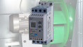
Figure 1. An example of a pre-built star-delta motor starter. Image used courtesy of MSC Industrial Supply
What’s the Difference Between Wye and Delta Motors?
Before diving into how they are wired, we must understand the differences inside the motors.
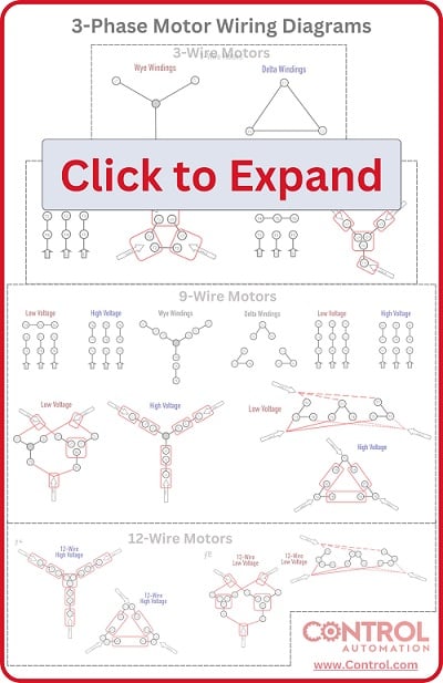
There are four distinct wiring patterns inside 3-phase motors (check out the header links for a deep dive into each pattern), and for star-delta to work, the motor must be able to fully switch between the two patterns:
3-Wire Motors
Inside the motor, the windings have been fixed into a dedicated wye or delta pattern, with the supply voltage also being determined at the factory. The most fool-proof, but most inflexible, and not very common. These can not be used for star-delta starting.
6-Wire Motors
Three independent windings with both ends accessible by the electrician. The pattern (wye or delta) can be changed, but the maximum voltage cannot be changed. If the motor will not be rated for high/low voltage. These can be used for star-delta, as long as the max voltage is observed.
9-Wire Motors
The most common configuration, these have one dedicated wye or delta inside the motor, with three independent windings accessible by the electrician. The voltage (high/low) can be configured by the wiring, but since they have a fixed wye or delta inside, they can not be used for star-delta starting.
12-Wire Motors
The most flexible of all motors, these have six independent windings, with both ends of each winding accessible to the electrician. By wiring them in series or parallel, they can be used to form either delta or wye patterns, in either high or low-voltage configuration. Since they can form both patterns, they can be used for star-delta starting.

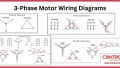
Figure 2. The two types of motors that can be used for star-delta configuration: 6-wire and 12-wire motors. Image used courtesy of the Control Automation engineering team
How Does Star-Delta Work?
Now that we know which motors can be used, the common denominator is that the motor must be capable of being wired as a star (wye) and as a delta motor.
When the motor is started, the wiring must be in the star (delta) pattern. This pattern places the windings in series with each other, which means that when the phase lines are provided with the full supply voltage, each winding will be provided with a lower voltage than if only one winding existed between phase lines (that’s how series circuits work).
When the motor starts up with this increased resistance, the voltage dropped by each winding is lower, and therefore the current draw is lower. But beware: the starting torque is also much lower!
Once a short startup time has elapsed, the motor reverts to delta configuration, where only one winding exists between supply leads and each winding receives the full supply voltage, thereby full current and full torque. This is a sort of parallel configuration.
To be specific, when a motor is supplied with 208 volts in a star (wye) configuration, each winding will receive 120 volts (rated voltage/sqrt(3)). That equates to a power consumption equal to (rated voltage/sqrt(3))*(rated current/sqrt(3))=(rated power/(sqrt(3)^2). In calculation, (1/sqrt(3))^2 yields only 33% of the rated power and torque.
Comparing this to the delta configuration, where each winding receives 100% of the rated voltage, current, and torque, it is easy to visualize both the beneficial reduction in supply current (lower cost and infrastructure demand) and the detrimental reduction in torque (smaller loads).
How Do You Wire a Star-Delta Starter?
Understanding a starting method and actually using it are two entirely different matters.
There are two main options for this starting method. The first involves three separate devices: two 3-phase contactors to supply power plus another contactor with three poles, able to create the center of the star (wye). The second method uses a dedicated star-delta starter, which supplies all of the previous devices, but in one single (and often $$$) device.

Figure 3. Diagram of wiring a star-delta starter, with each step labeled in blue. Image used courtesy of the Control Automation engineering team
Wiring a Star-Delta Starter
We will use a 6-wire motor as an example. If you have a 12-wire motor, join T4-T7, T5-T8, and T6-T9 and you have 6 wires left over.
1. The first motor contactor (C1) is connected to T1, T2, and T3, the ends of each of the three windings. Connect the input side of this contactor to the supply L1, L2, and L3.
2. The second motor contactor (C2) is connected to T4, T5, and T6 (which would be T10, T11, and T12 if you have a 12-wire motor), which are the other ends of each motor winding.
Unlike a reversing motor starter, these contactors are NOT interlocked, there will be a very good reason to have them both energized at the same time…. But not yet.
3. To the input side of this second contactor (C2), bond incoming L1 to L3 of the second contactor, incoming L2 to L1 of the second contactor, and incoming L3 to L2 of the second contactor.
Note: DO NOT USE a reversing bus bar for this operation since it only reverses two of the three leads, and you will end up with a short-circuit.
4. Finally, to the third contactor (C3), connect T4, T5, and T6 (again, this would be T10, T11, and T12 if you have 12-wire motor), and jumper all three of the incoming terminals to each other. This will create a single connection between all three when the contactor is energized.
To use the new wiring setup at initial startup, energize C1 and C3 while keeping C2 de-energized.
After a short time (determined by the load factor of the motors), de-energize C3 and then quickly energize C2. C1 stays energized the entire time.
This works because during startup, each winding is supplied with full voltage, but the other sides of all windings are bonded through C3 to create a star (wye) with lower voltage. When switched to run mode, the windings are now connected in a perfect delta pattern with full voltage.
Is Star-Delta Better Than a VFD?
To run a 3-phase motor, the go-to solution these days is almost certainly a VFD. Although reduced voltage starters used to be very common when digital controls were more expensive and rarer. The most likely scenario to encounter these starters is during maintenance on older equipment when advanced parameters weren’t necessary, just a reduced startup load.
Think it might be time to upgrade to a VFD? It may well be worth it, but the project is worthy of research before you start ripping out wires. In any case, it’s valuable to understand the many strategies for starting and running large motors.
Interested in more content about motors? We have plenty to choose from!
Articles:
- 3-phase Motor Types: Synchronous and Induction Motors
- Understanding Delta Wound Motors for Industrial Applications
- Common Motor Windings and Wiring for Three-Phase Motors
- Brushed vs. Brushless DC Motors
- Field-oriented Control (Vector Control) for Brushless DC Motors
- Teardown: What’s Inside a 3-Phase Induction Motor?
Textbook: