Facebook
 Google
 GitHub
 Linkedin
What is a Stepper Motor, and How Does it Work?
When the angle or distance of motion is more important than speed and power, certain motors shine brighter, like steppers, named for the individual steps they take when control voltage is applied.
Imagine designing a machine that must cut precise holes and grooves in a blank metal sample. You connect a simple DC motor and judge exactly how long it takes to move 1.000 inches. Using this sample time, you design a complex program to machine all the various features of the part. On the first run, the motor, being slowed down just slightly by the interaction of the bit with the part, does not move as far as you wanted.
This is a poor example of precision control. I don’t mean to say that DC motors are poor in design, simply that their strength is not in precise starting and stopping at exact distance intervals. This is also true for AC motors.
In these cases, we turn to more advanced motion solutions, including both servo motors (where a measuring device and algorithm are strapped to the end of a DC or AC motor), or we can use a stepper motor, a specialized mechanism that drives extremely precise motion without the need of an extra measuring feedback sensor.

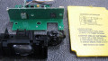
Figure 1. The complete view of the components in a NEMA 34 stepper motor.
What are Stepper Motors?
A stepper motor is so-named because the stator and rotor interact with many more points of magnetic interaction than DC and synchronous motors. Most stepper motors have 200 of these interaction points distributed around the inside of the motor. With 200 steps, this yields a precision of 1.8° for each step.
For more advanced control, some of the coils can be supplied with partial current, and in both positive and negative directions, leading to a concept called ‘microstepping’ which can advance the motor in tiny fractions of the standard step distance. Some microstepping algorithms can produce up to 256 microsteps for each full step, meaning a precision of 0.007° for each step. This sounds great, but due to a lowering of holding torque, it really only works well for very low-torque applications.

Figure 2. The outside (stator) of the motor contains the windings, which can be fully or partially magnetized, often in both directions, for exceptional control.
Because of the priority of precision over speed, these motors are not used to drive heavy loads or at a high continuous speed. The control circuitry required increases the complexity and lowers electrical efficiency. Think about it, would you rather write a program and include a special add-on motion module just to drive a motor… Or simply connect the two leads to a supply voltage relay? They excel in start/stop applications where precision is needed: CNC axes, linear stages, 3D printer frames, inspection camera motion, etc.
How Do Stepper Motors Work?
Internally, a stepper motor looks more like an AC motor than a DC motor. A typical DC motor needs brushes to alternate the voltage going to the magnetic coils of the rotor. However, an AC motor uses the natural alternation of the electricity to excite the windings around the outside of the motor, while there is no connection to the ferrous core of the rotor. If we look inside the stepper, it will be reminiscent of an AC rotor.

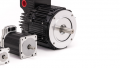
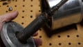
Figure 3. The rotor of a stepper motor does not have commutators or brushes like a normal DC motor.
To maintain motion in a predictable direction, the poles (the points of magnetic interaction) on the rotor and field windings cannot be aligned perfectly. If they were, the motor would advance one full step, then with the next control signal, the motor might move randomly either CW or CCW to reach the next step, and this could be disastrous.
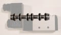
Instead, the number of poles on both the rotor and the stator are not equal, so there is no possible way for them to align all the way around. When a coil set is energized, the small teeth visible on the rotor will push or pull the rotor to perfectly line up with the proper coil and hold it firmly in place. Then, the next control signal will energize the next set of coils, and the rotor will move another 1.8° and hold in place once again.

Figure 4. The number of poles on the rotor and stator do not match, so they are aligned in some places, but all the way around.
To reinforce the concept of microstepping, two coils may each hold an equal attraction to one of the teeth, holding that tooth halfway between the coils. This would mean that two unique steps can be reached for every one step in standard motion. Further distribution of voltage between coils can microstep with more precision.
Because the rotor is being pulled in two directions with microstepping, it actually becomes easier to rotate the motor by hand (or by external load) since two magnetic fields would both like to pull the rotor. This means that holding torque is lowered quite significantly as the microstepping force becomes more uneven.
How Do You Drive a Stepper Motor?
Naturally, as you can visualize a CNC machine axis, we would need the motor to move at different speeds depending on the scenario: different material feeds, rapid transit between points, homing, etc. There must be a way to control the speed of alternation to the coils, much like a VFD for a 3-phase motor.
The stepper motor controller boards are designed for 4-wire, 6-wire, and 8-wire stepper motors. Each of these wiring scenarios can produce a DC voltage across the coils in two directions, to either push or pull the rotor, but any step motor will only be wired for one of these setups. You must know what motor you have in order to select the proper driver board.

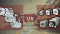
Figure 5. Wiring schemes for 4-wire, 6-wire, and 8-wire steppers.
4-Wire Stepper Motors
The motors with 4 wires are bipolar, which means that two coil sets are distributed around the rotor, each coil set can be driven with positive or negative (bipolar) voltage.
6-Wire Stepper Motors
6-wire motors contain two coils, each with a center tap. These are usually unipolar (one direction of voltage), with the center tap being positively charged, and the two coil ends alternately grounded. In some cases, the center tap can also be alternated which leads to a bipolar 6-wire motor, but this is due to the driver board’s capabilities, not the motor. It’s still a 6-wire stepper motor.
8-Wire Stepper Motors
Finally, the most complex motor has four alternating sets of coils which can be connected individually to an 8-wire driver board, or they can be bonded externally with a center tap to create a 6-wire motor, or finally, they can be connected externally in series or parallel to form variations of a 4-wire motor. Flexible, but more complex.
Control Signals for Stepper Drivers
A controller (like a PLC or motion controller) sends a set of signals to the stepper driver. The signal will contain a transitional edge (trigger) pulse as well as a direction for step-direction input. Alternatively, a transitional pulse could be provided for forward or reverse direction (CW-CCW input). Most driver boards follow the first (step-dir) scheme.

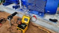
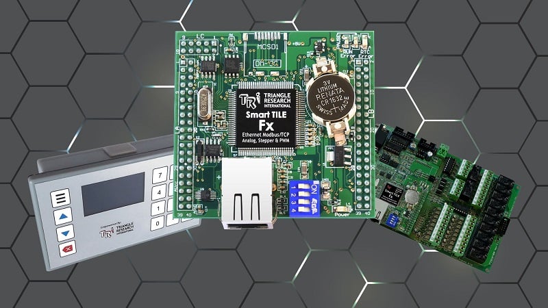
Figure 6. Several sizes of step motor driver boards.
Choosing Stepper Motors
Four main characteristics define a stepper motor. The first is the number of wires, which we have already discussed. The holding torque, usually expressed in oz-in, determines how much force can be applied back against the motor before slipping. The current in each coil (in mA or A) must be supplied by an appropriately sized driver board. Since most drivers can supply various adjustable output voltages, the resistance of the windings should be matched to a current set limit in the driver.
Following the right design steps for a stepper can be tricky, but they are a great asset in the design and construction of precision linear motion in all kinds of applications.
All images used courtesy of the author
Interested in more content about motors? We have plenty to choose from!
Articles:
- 3-phase Motor Types: Synchronous and Induction Motors
- Understanding Delta Wound Motors for Industrial Applications
- Common Motor Windings and Wiring for Three-Phase Motors
- Brushed vs. Brushless DC Motors
- Field-oriented Control (Vector Control) for Brushless DC Motors
- Teardown: What’s Inside a 3-Phase Induction Motor?
Textbook: