 Facebook
 Google
 GitHub
 Linkedin
Power Supplies: Understanding the Differences Between Linear and Switching
Linear and switch-mode power supplies provide direct current to power control components and electrical devices. Learn about the differences between the two power supplies and which one is best for your control system.
Power Supplies in Industry
Alternating current (AC) power is created in a generator or alternator and continuously switches polarity as the generator spins. This type of electrical generation has an advantage over direct current (DC) power because it is able to travel large distances more efficiently. Since almost all supplied power is some form of alternating current, it is the primary type of electrical power used to power most industrial equipment. Once the power reaches industrial equipment or any form of automation, it often needs to be changed to a more useful type of power for individual electrical components within the cell.

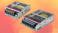
Figure 1. Linear (left) and switching (right) power supplies. Although subtle, the difference in physical size can indicate a larger transformer in the linear power supply. Image used courtesy of Matsuda Precision
Every automated cell, robot, or industrial machine requires some kind of control panel or control system. Depending on the complexity of the different types of equipment, parts within the control panel will need certain types of electrical power. Power supplies are used to supply these components with the specific power they require, whether that is low-voltage DC power or an AC power connection that is a different voltage from the incoming power. Most control components and electrical devices run on some form of low-voltage DC power, so the alternating current supply needs to be changed into the correct form of DC power needed for the electrical device. The piece of equipment used to change the AC power is known as a DC power supply.
There are two different ways to create a power supply, and they fall into the category of linear power supplies and switching power supplies. They both have advantages and disadvantages, all to be considered in the design process of a robotic or automated cell. Depending on the application, many cells contain one or both types of power supply specifically suited for each individual application.

Figure 2. A linear power supply schematic.
Linear Power Supplies
Linear power supplies are used in different applications throughout the electronic and automation industry. They are known for their quiet operation in comparison to switching power supplies. In addition to low noise operation, linear power supplies create stable DC power with low ripple. Ripple in DC power supply is the amount of superimposed AC present in the supplied DC power. In other words, linear power supplies are capable of making very smooth DC power from AC.
Linear power supplies generally work by decreasing high-voltage alternating current to lower-voltage alternating current through the use of a transformer. After the transformation, the lower voltage AC current is run through a rectification process where the AC power is converted to DC power.
Because of the nature of the process through which the change from AC to DC happens inside a linear power supply (particularly the transformer and relatively large capacitors), they are usually quite large in comparison to switching power supplies and less energy efficient.

Figure 3. A switching power supply schematic.
Switching Power Supplies
Switching power supplies are similar in nature to linear power supplies, but their operation switches every time the supplied current alternates. Switching power supplies work by using pulse-width modulation (PWM). PWM allows for an efficient change from AC to DC power, reducing energy waste within the system. They are also smaller in size than linear power supplies, as the VA (power) rating of the transformer on a PWM duty cycle is much lower.
Small size and energy efficiency does come with a cost however, and switching power supplies produce significantly more electrical noise than their linear counterparts. The noise is created from the constant electrical switching generated within the unit.
Switching power supplies also have one other advantage over linear supplies, they can either step up voltage or step down voltage, making them useful in applications where voltage needs to be increased. Linear power supplies are incapable of stepping up voltage. Switching power supplies are also capable of using different types of AC input to create steady DC voltage out the other side. In the case of linear power supplies, the supply will need to be manually adjusted to fit different input voltages, a slight disadvantage for applications without standard AC power input.

Figure 4. Inside a linear power supply (left) and a switch power supply (right) is a transformer, a rectifier circuit, a smoothing circuit, and a low pass filter. Image used courtesy of Konstant Lab and Sparkfun
What’s Inside a Power Supply?
While the components inside of a linear and a switching power supply are different, they do have an overlap of components. They both contain some type of transformer, a rectifier circuit, a smoothing circuit, and a low-pass filter. The way that these components interact with each other is different, however, and they each contain individual components unique to their type of switching circuit.
Linear power supplies require a transformer to reduce the incoming AC voltage. Once the voltage is reduced, the AC power is put through a rectifier circuit that consists of a diode bridge. The voltage that leaves the rectifier circuit is not smooth at this point in the process, and a smoothing capacitor in conjunction with a control circuit is used to even out the voltage. The difference between the voltage peaks creates excess heat so a heat sink is necessary to protect the linear power supply. Once the voltage reaches the other side of the circuit, it has been successfully changed to DC current with a low amount of noise.
Switching power supplies contain similar components, but the process for changing the current is much different than a linear power supply. In switching power supplies, the power is rectified and smoothed before the voltage is transformed. A high-frequency transformer is used to take the voltage up or down the appropriate voltage before being smoothed again in a control circuit that contains a switch. The final rectifying and smoothing part of the circuit contains a low-pass filter in conjunction with the control circuit.
Linear vs Switching Power Supplies
High voltage AC current is efficient for moving electricity large distances from the place of generation, making it optimal for power transfer. High voltage AC has limitations when it comes to effectively powering the small sensitive electrical control equipment and electronics necessary for automated equipment. Because of this limitation, high voltage AC current often needs to be changed into lower voltage DC current.
DC power supplies are an effective means of changing the type of current to make it more useful for control components. Linear power supplies offer a smoother, less noisy form of DC power supply, but are less energy efficient and cannot step voltage up. Switching DC power supplies are more energy efficient and can step up or down voltage, but are more noisy electrically because of the continuous switching.


I enjoyed reading this article and thank you for taking your time to writing. I lack knowledge in this topic but shouldn’t the transfer come before full wave rectifier in switch mode power supply?
The advantage of placing the transformer after the rectifier/filter is that the resulting DC can be converted to pulsed AC to feed the transformer at a significantly higher frequency than the incoming line voltage. The advantage is that a given amount of power can be magnetically transfered through a much smaller transformer if the operating frequency is increased significantly. That means lower cost, size and weight at a given power level. It seems overly complex to convert AC to DC, then to high-frequency AC, then back to DC, but to put it simply, iron and copper (i.e. the transfomer components) are more expensive than the required electronics.