Facebook
 Google
 GitHub
 Linkedin
Power Supply Troubleshooting and Testing
This article discusses the proper steps for testing the supply for proper function.
Whether you're using an industrial DIN-rail power supply or a linear supply for an audio application, these devices can fail. There are a few simple and some not-so-simple methods of testing a power supply for proper functionality.
Locating the faults in a system so often seem to return to the most straightforward problems. When many parts of a system, such as the sensors on a machine, or an entire PLC, go dead, that might indicate faulty power supply, and the devices themselves are just fine.
Testing power supplies is usually a quick process, but some results can be misleading without the right information.
How to Test Power Supply
Different types of power supplies also may provide differing abilities to be repaired. In many cases, once you identify a faulty supply, it's much more efficient to replace the supply. Below are a few steps necessary to test the power supply.
Test the Supply with a Voltmeter
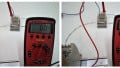
The first step is to test the supply with a voltmeter. How do you test a power supply with a voltmeter? This step can be tricky. Is it more useful to test the input terminals or the output? The answer may depend on the symptoms.
If we see that everything receiving power from the supply is turned 'off' and the supply is the primary suspect, you can first check the input terminals. If the input is properly receiving power, we can eliminate any problems from upstream. The problem must be limited to the supply or after. Set the meter to measuring AC if the supply is powered from single or 3-phase power.
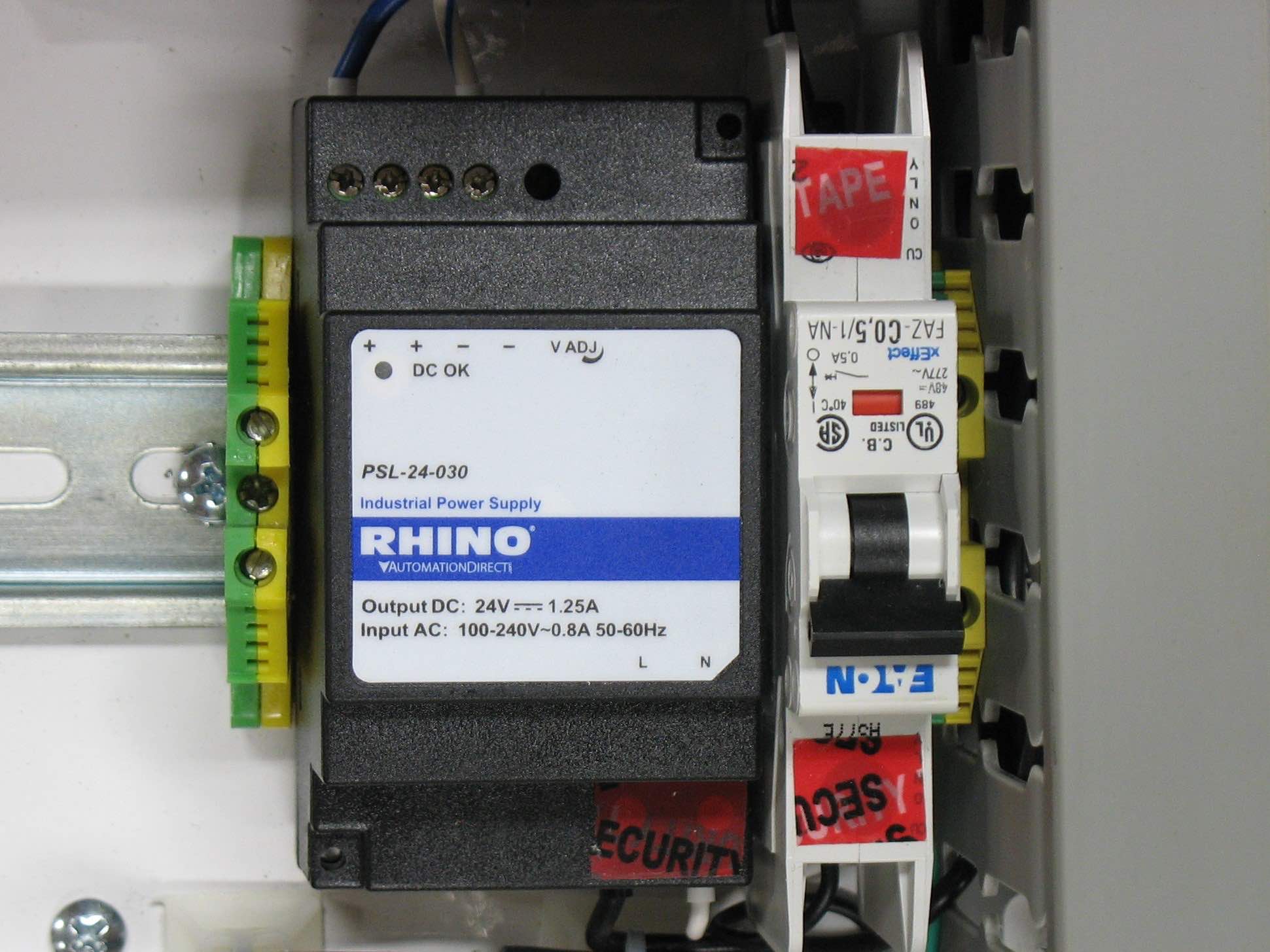
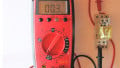
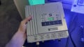
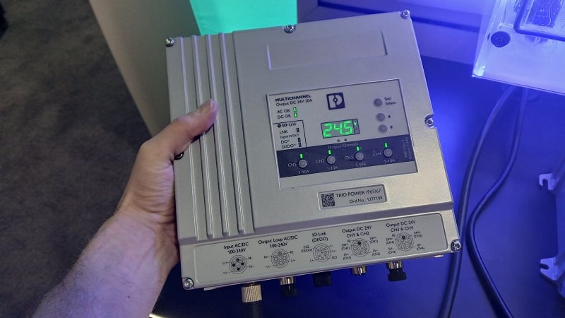
Most industrial power supplies use 1- or 3-phase input power. They also often have a voltage adjustment screw terminal, indicated here with 'V ADJ' with the curved arrow.
On the other hand, the output is the main factor determining whether the devices will be receiving proper power. Testing the output terminals should yield something very close to the rated output voltage.
Industrial power supplies can sometimes be adjusted within a small range to fine-tune the output, but this is designed to compensate for loading effects.
It would help if you planned to adjust this at the very beginning of the installation. It should not increase the voltage if it should suddenly drop one day after years in service.
Sometimes testing the output is complicated, like on a phone charger USB cable. The terminals are extremely difficult to access.
However, most of these tiny, inaccessible power supplies are very inexpensive, and replacement is the most obvious choice. If testing is essential, breakout boards can be purchased.
These boards turn the tiny cable into a larger prototyping board with terminals than can be easily reached. I try to keep a couple of these types of boards around in my shop all the time.
Load Conditions
In the previous step, I discussed the testing without respect to the load. Should it be connected when performing the test, or not? The correct answer is both. First, test the output with the load is disconnected (open-load voltage). If this voltage is correct, it means that the problem is in an over-load, perhaps a short-circuit, downstream. If the open-load voltage has suddenly become too low or has turned off entirely, the power supply is probably the faulty component.
Again, be sure to test the input voltage before this step. If there is no input, then there should also be no expected output - the power supply is not the fault.
Once the open-load output is verified, then the load test should be completed. This is the real-world test since the open-load voltage isn't actually what we are trying to determine.
We need to know if the power supply can still function when the devices are connected. Reconnect the load wiring and check to see what happens. It should be one of two scenarios:
The output voltage should reduce slightly. This is normal. If the current is being drawn through the load, the source voltage will always drop. However, the drop should not be significant, but it's hard to tell how much this should be. All that can be said is, "If the drop is too much, the power supply is failing and cannot keep up." Reduce the load or replace the supply.
The output voltage may drop to zero. This is common in supply with overload protection like many industrial supplies. Too many load devices can pull too much power.
Miswired or failed load wiring can create short circuits. If the load current is above the rated maximum, the output voltage will drop to zero. As soon as you remove the load, the voltage is restored. Find the source of the overload and remove it.
Component Testing
Linear and switching power supplies both provide output voltages, but the method is quite different. When you plug in a switching supply, many components inside are connected to the main line voltage. It is not advised to test or repair inside a switching supply unless you have the right tools and training.
Linear supplies tend to be more expensive, which means that repair might be more efficient. Even still, hours of testing and repair may be more costly than a whole new supply. The structure of a linear supply is relatively simple, so testing isn't too bad.
First, a transformer (usually a large one) will have an input primary coil side with the supply AC voltage across it. Often there is a fuse in-line or even built into the transformer. This may be the overloaded component. The secondary coil voltage should be stated somewhere on the datasheet or the part sticker and measured as AC voltage.
Second, a bridge rectifier consists of two diodes always in series with each other at any time. The following components, such as the capacitor, will now show DC voltage. Be careful when testing capacitors as they can often store a dangerous charge, but the high impedance of a voltmeter creates a safe test for these relatively low voltage supplies.
You can only correctly measure the section between the rectifier and the regulator with an oscilloscope.

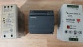
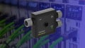
This linear power supply has a fuse (center) in-line with the transformer on the right side, clearly visible primary and secondary terminals, the bridge rectifier at the top, and a capacitor on the left.
This supply type would be quite expensive, and the ease of component replacement might make a favorable repair.
A voltage regulator is a final component before the load terminals. The regulator's output should be a smooth, constant DC output and test with a DC voltmeter.
Sometimes the output is an adjustable linear supply, like with a common benchtop double or triple-output supply. You can also test these regulators, but there needs to be some method of calculating the correct output voltage, or the measurement will be meaningless.
Testing power supplies usually does not include testing the internal components. Component-level testing is rarely done for switching supplies.
First, test the input voltage, then the open-load output, and finally, the output with the load connected, and the source of the problem should be traceable. Yet, the fault can be corrected or the power supply replaced as required.