Facebook
 Google
 GitHub
 Linkedin
How to Troubleshoot Mechanical Relays
In this article, we will discuss the main causes of failure in mechanical relays, as well as look into simple methods of testing relays using common hand tools.
Since relays are such a fundamental part of control system architecture, it must be useful to design simple, effective troubleshooting methods.
Taking extra time to identify faulted components is a costly and inefficient practice, especially when simple techniques are available to troubleshoot and repair equipment.
Mechanical and solid-state relays are common components that are often at fault for failed control systems. Although problems can certainly stem from other components, it can increase troubleshooting efficiency to investigate the common components first.
| Check out our exclusive ebook: The Complete Guide to Relays! |
What Causes Relay Failure?
Most times, the culprit of relay damage is a spike in voltage to either the coil or the contacts, or by an improper power supply to the terminals.
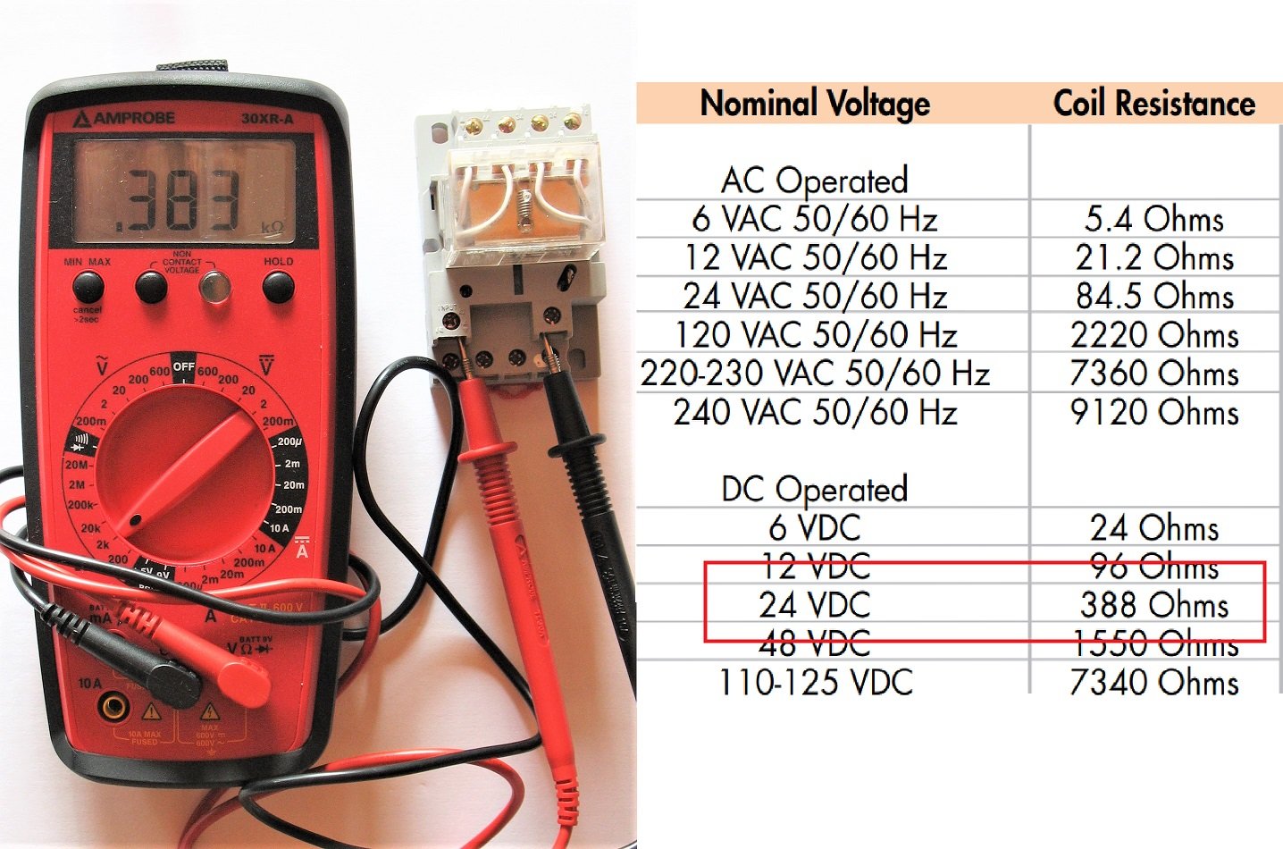
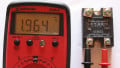
An ohmmeter showing 383 ohms of coil resistance. This datasheet excerpt shows that this relay is stated to have 388 ohms - this one is nearly perfect.
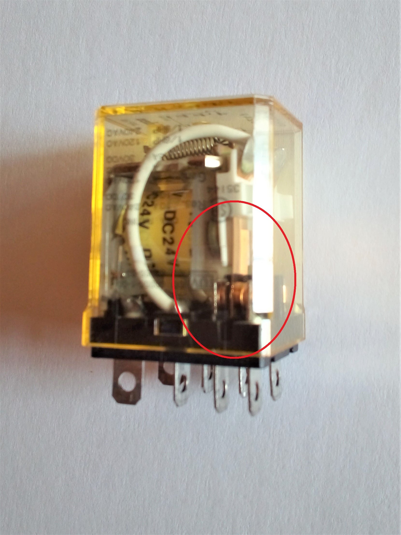
The input terminals will send power to the coil of a mechanical relay. Each of these relays will have a very specifically stated voltage or range of voltages tolerated. Exceeding this coil voltage will cause failure.
In a mechanical relay, the coils will begin to overheat, causing the resistive wire coating to melt, and fusing turns together inside the coil.
If the voltage was only a momentary spike, it may result in a reduction in turns, which will both lower the resistance as well as lower its ability to generate a magnetic field, and the contacts may not energize. Be careful though, because an indicator LED may still indicate a functional relay. In a solid-state relay, the excessive voltage will likely cause instant unrepairable failure.
In many cases, an extremely high voltage spike may cause instant failure due to an arc between coil and contacts, or between sets of contacts. This may happen in either mechanical or solid-state relays, but is most common when an inductive load such as a contactor or solenoid valve is the output of the contacts.
When this solenoid is turned off, a large voltage spike occurs (often accompanied by a visible spark) and the life of the relay is greatly reduced and the contacts can be welded together. If the relays are inside a PLC or other digital control device, it can also be a very expensive failure.
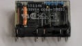
A close-up view of the contact pads on a mechanical ‘ice cube’ relay. This relay is nearly new, but a damaged contact may show black marks on the contact pas or even on the plastic case.
The other cause of failure is an electrical failure caused by an excessive number of switching actions. This is different than the mechanical failure of broken parts that may be experienced in a mechanical relay, although this is uncommon.
The electrical failures result from repetitive switches, which cause small arcs on the contacts. Eventually, the low resistance plating will corrode, causing higher resistance. This is evidenced by black marks on the contact pads and excessive heat from the higher-than-normal voltage loss. Higher voltages will cause this corrosion to occur more quickly.
Understanding Relays: Testing Input Coils
Testing the coil of a relay involves determining whether the resistance is more or less than it should be. First, remove one of the wires from the terminal on the socket, or remove the relay from the socket entirely. Use an ohmmeter to measure the resistance of the coil, being prepared for three different values.
If the reading is OL, this means the value is beyond the measurement range of the meter, or the coil is ‘open’. Note that the indicator LED may still illuminate since it’s in parallel with the coil. Even if the coil is bad, the LED may still turn on.
If the reading is less than around 5 ohms, this also indicates failure. Most likely, the wire insulation has been melted and the number of turns of wire have been greatly reduced, resulting in a ‘shorted’ coil. In this case, it is likely that an input fuse or breaker had been tripped due to the increase of load current. If that was the case, investigate for shorted coils, not open wires.
Finally, the value may be somewhere in the range of 100-1000 ohms, making the determination more difficult than a simple instant evaluation. You need to have a datasheet available, or a known working identical relay on hand to compare the value.
If the resistance of the coil is less than the datasheet or known good value, it is likely that the number of turns has been reduced and there is not enough inductance to generate the magnetic field required to switch the contacts.
Testing Output Contacts
After the coil has been determined functional, move to the contact terminals of the relay to continue testing. Use the ohmmeter to measure from the common terminal to the normally closed terminal first. If a manual toggle switch is provided, you may also test the normally open terminal. The resistance will most likely be one of two values.
In a functional relay, the resistance between the common and normally closed terminal should be no more than a fraction of an ohm. A datasheet will show an exact value and tolerance to expect, but 0.05 ohms is common, or 50 milliohms.
Make sure you test your multimeter leads before making a determination - the resistance of just the leads alone may be close to 0.5 ohms, this would affect your readings significantly! If the resistance of a closed contact is above the upper tolerance limit, it could result in too much voltage loss and heat dissipation in the contacts. Old, well-used relays will show an increased contact resistance, especially if they have been used to switch 110 volt AC loads.
Many multimeters will not be able to measure resistances that low, so it can be difficult to judge in those cases. However, a test of voltage in a live circuit across the contacts will show the millivolts lost by the contacts. Compare this voltage drop to that of a known working relay in a functional circuit in order to make a better measurement.

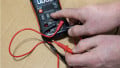
A sample ohmmeter measurement of a normally closed contact. This meter is not precise enough to measure 0.05 ohms, and also it shows the additional resistance of just the leads.
In these cases, it might be necessary to measure the small voltage drop in an active circuit to troubleshoot the relay.
If the relay is equipped with a toggle switch, then flipping this switch should immediately change the reading to OL, or ‘open’ This means that it has switched properly.
For absolute certainty, a bench test would involve powering the coil with the appropriate voltage and testing the resistance (or the voltage, as described above) of both the normally closed and the normally open contact resistance. They should switch between 0.05 (approximately) and OL.
Mechanical relays can be a difficult subject to troubleshoot and test. However, it helps to break them into their individual components - the coil, and contacts. In an isolated component, both the coil, and the contact resistance can be measured. In a live circuit, the voltage drop of the contacts compared to a working relay may give a good indication of a relay that may have failed.
Love relays? So do we! Check out our whole collection of relay content:
- Differences Between Electromechanical and Solid State Relays
- Info Byte: What’s the Reason Behind Relay Terminal Numbering?
- Info Byte: Preventing Relay Burnout with Flyback Diodes
- Understanding the Differences Between Protection Relays vs Control Relays
- Info Byte: The Mystery of Ice Cube Relays–Coil Polarity
- I/O Module Debate: Digital Output or Relay Output?
- Contactors versus Relays - Differences and Applications
All images provided by the author.