Facebook
 Google
 GitHub
 Linkedin
How to Troubleshoot Encoders with an Oscilloscope
In this article, learn the different errors that keep an encoder from working correctly and how to troubleshoot issues using an oscilloscope and other T&M tools.
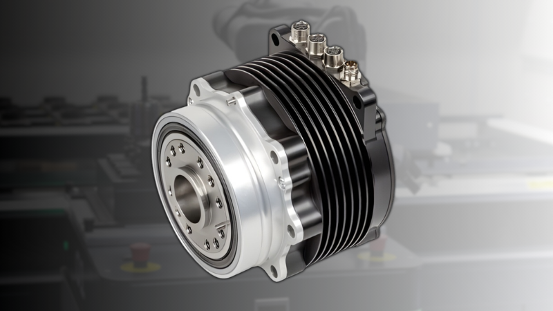
The encoder is an electro-mechanical device used to identify the angular position of the shaft of a motor by converting mechanical motion to digital signals. Rotary encoders are the most commonly used variety of encoders, although there are niche use cases for linear encoders.
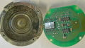
Optical sensing is a widely-implemented technology for encoders. An interrupter disk with evenly spaced cut-outs is coupled to the rotor of the encoder. An LED light source with a photodetector is aligned with the cut-out channel of the interrupter disk. The photodetector produces a pulse when the light passes through the cut-outs when the rotor rotates. The output of an encoder’s digital signals depends on the number of channels in the interrupter disk.

Figure 1. Inside a single channel rotary encoder. Image courtesy of Ryan VanOtterloo.
In most cases, at least two channels are cut out on the interrupter disk. Encoders with higher resolution requirements have multiple channels, sometimes up to a dozen. The photodetector outputs a pulse of maximum voltage when light hits it and there is no voltage when there is no light. Therefore, the output from the encoder will be digital signals. If the encoder has a single channel interrupter disc, there is only a pair of output cables.
A dual-channel interrupter disc has two sets of output cables. The number of output cables is twice the number of channels on the interrupter disk. The digital output is used to calculate speed, angular shift, and direction of the motor.
Testing Encoders Using an Oscilloscope
An oscilloscope is required to test an encoder. An oscilloscope is a test instrument that displays varying voltage to be tested on a two-dimensional graph as a function of time. They can be used to observe and compare the amplitudes, frequency, and direction of the signals from an encoder.
The cut-outs on the interrupter disks are designed in such a fashion that the output signal from one channel will be, in equal amounts of time, high voltage and low voltage. The output from the encoder can be observed as a square wave with a 50-50 duty cycle due to this reason.
The duty cycle is a fraction of the period in which the signal is active, where period refers to the time taken to complete the on-off cycle. The two channels in the interrupter disks are designed in such a manner that they are offset 90° from each other. This offset helps to distinguish between the clockwise and counterclockwise rotation of the rotor.
One high voltage or low voltage section represents 180° of an electrical rotation. Half of that duty cycle represents 90° of an electrical rotation. The output cables of the encoder are connected to a dual-channel oscilloscope to observe the output waveforms and should look like the image shown in Figure 2.

Figure 2. Signals from the two channels
If the signal from AA` has the same amplitude and frequency as the signal from BB` with a 90° shift, the encoder is working correctly. If not, the encoder needs to be repaired or replaced.
Troubleshooting Different Problems With Encoders
When there are troubles with an encoder’s operation, it is advisable to check the mechanical and environmental factors before troubleshooting it. It may very well be a case of shorted wires, loose coupling, or other environmental issues. Basic checks like checking the input voltage and the wiring connections must be done before going to the next steps in troubleshooting. If a similar working encoder is available, swap it with the encoder in operation to determine whether the problem lies with the troublesome encoder.
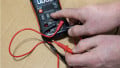
Using a Multimeter
A simple multimeter can be used to measure the parameters of an encoder. A multimeter can measure the average voltage, peak voltage, frequency, and duty cycle of a rotary encoder. This can be compared against the standard output indicated by the manufacturer and can determine whether the encoder is faulty or not.
In most cases of trouble with an encoder, the values measured by a multimeter would appear to be normal even if the encoder is experiencing some trouble. In such cases, an oscilloscope is a must for troubleshooting.
Encoder Jitter
Jitters appear as backward and forward movement of the pulse on an oscilloscope. Jitters are caused due to a decentered interrupter disk. As the decentered disc moves within the casing, the two channels appear to move relative to one another. This will cause the phasing between channel A and channel B to change every rotation.
The characteristic of encoder jitter is that the jitter will only appear on one of the channels. If the signals appear to be jittery in all of the channels, it could indicate trouble with the oscilloscope or an error other than encoder jitter. If it is determined as an encoder jitter, the part should be sent to the manufacturer to repair or replace it.
Signal Flicker
A signal flicker is a sharp spike in the output signal. It can be confused with encoder jitter. However, encoder jitter shows a consistent pattern in phasing variation while signal flickers appear to be random. Some encoder installations enable interpolation to improve the effective resolution of the output. In such cases, a signal flicker is part of normal operation. If interpolation is utilized, it is part of the device specifications. In the case where signal flicker is observed, consult the device datasheet to check whether it is part of normal operation.
Extended Encoder Pulses
When the leading or trailing edges of the output pulses are elongated, the counts of the number of times a cut-out on a channel is crossed can be read incorrectly. This can lead to the speed and the position of the shaft to be calculated falsely.
Mounting issues are the common cause of extended encoder pulses. A small and occasional effect on the pulses may be due to a loose coupler and is an easy fix. When a loose encoder turns with the motor shaft, it shows as broad, extended pulses on the oscilloscope. Extended pulses do not signify a problem with the encoder. Rather, the problem is likely due to poor mounting of the encoder with the motor and can be fixed with a proper reinstallation of the device.
Low Amplitude Signals
Low amplitude signals appear to be square waves but the amplitude is quite a bit lower than the specifications of the device. The amplitude of the signal will be too low to be read by the controller or PLC. This is commonly due to poor wire connections or crosstalk from different channels. Again, this reading does not indicate a faulty encoder. Checking the connections and reconnecting the encoder will sort out this issue.
Shark Fin Pulses
The rising edge of the pulse has some delay to reach the full amplitude. On the oscilloscope, it appears as a rounded curve similar in shape to a shark fin. This hinders the controller or counter cleaning detecting the pulses. This could be due to long cables that are used to transport output signals. Low capacitance, twisted pair cables can be used to reduce this distortion.
Other reasons for the delay could be the load, speed, and/or the resistor of the encoder. In general, when the resolution of the encoder is high, the time delay will be higher.
Stepped Encoder Pulses
With stepped encoder pulses, the output signals on the oscilloscope will appear to rise and fall in amplitude in multiple steps than a single step. This makes it difficult for the receiver of the signals to accurately count and causes an error in speed and position calculations. The steps will appear identical in all of the channels. This error is due to the shorting of various cables on the output side of the encoder and can be easily rectified by removing any stray wires, open insulations, or the shorted cables.
Related Content