 Facebook
 Google
 GitHub
 Linkedin
Troubleshooting Solid State Relays
This article discusses some methods for troubleshooting solid-state relays and input/output terminals.
Solid-state relays are semiconductor devices that can allow large currents, but if their input and output rating are exceeded, the damage will be instant. This damage often cannot be seen from the outside, making them harder to diagnose. But with a few simple troubleshooting steps, it can be simple to verify proper operation.
Check out our exclusive ebook: The Complete Guide to Relays!
What Are Solid-State Relays?
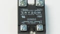
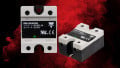
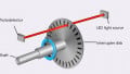
The basic operation of a solid-state relay consists of a small-voltage LED attached to the input terminals which can be rated for a range of DC or AC voltages. The output contacts are either a single high-current Field Effect Transistor (FET) or thyristor device, giving either DC or AC load switching, respectively.
Since these relays have no moving parts, they are more difficult to inspect visually and audibly than the mechanical components. The solid-state components inside both the input and output sides depend on diode junctions for operation, so some of the test methods resemble diode test functions. Unlike mechanical relays, they cannot be tested using resistance alone
There is one difficulty that arises when testing these relays. Since they are constructed from semiconductor components, they will respond differently based on the amount of voltage applied to the outputs, and the type of output (FET vs thyristor).
Since different meter brands and models will output different voltage and current levels to perform certain tests, you can’t always count on expecting a particular result. When performing many of my own tests with various meters, I measured different values from the exact same relay using different meters. This is in contrast with any physical switch where contact terminals will fully open or close, providing obvious resistance and voltage expectations regardless of voltage level.
Testing Solid-State Relays
When performing measurements, keep in mind that no meter test will be a substitute for a proper bench test providing the exact operating voltage and current levels as the actual working conditions. These steps provided below are only a list of possible methods that might be used to track down a bad relay.
Input Terminals
The input of a solid-state relay is an LED placed in series with a current-limiting circuit. The current limit holds the flow to no more than 20mA usually, regardless of the input voltage. This is why they can accept a wide range of voltages. If they relied on a fixed input resistance, the LED would get brighter at higher voltages, so the output load circuit would respond differently as the input voltage changed. This isn’t ideal when the stated voltage is a range of appropriate values.

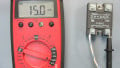
Using a diode test, the input terminals can be assessed for the operation of the internal LED circuit. Different meters may show a range of values between 1.2 and 2.0 volts.
Using any typical multimeter, the ‘diode test’ function is represented with the schematic diode symbol. This function places a small voltage onto a diode junction and slowly increases the voltage until the diode forward voltage is reached and current increases. This voltage is shown on the display. It is sufficient for testing LEDs as well as many transistors. Perfect for the DC input of a solid-state relay.
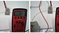
Place the red test lead of the meter onto the relay input terminal marked with a ‘+’. This will be present on any DC input relay. Place the black COM lead onto the other input terminal.
When the dial of the meter is placed in the ‘diode’ function range, the voltage should increase to around 1.2-2.0 volts. It may be slightly more or less, since each LED has a different operating voltage, and each model will have different outputs.
Misleading Results You May Find
Standard diodes do not need as much voltage as LEDs, so some meters may not be designed to increase their diode test voltage enough to activate the LED and provide a measurement. They will show OL on the display, but the relay might still work.
This will only work for low voltage DC input relays. If you find an AC or higher range DC that expects something above around 5 volts, the meter display will show OL, but the relay might still work.
Output Terminals
The amount of power consumed by a load of a normal relay far exceeds the tiny power output of the multimeter, so no meter can ever come close to simulating real-world conditions. Because of this, it might be expected that the output terminals can be trickier to troubleshoot, but we have a couple of options available.
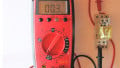
The diode test function can still work on a variety of DC output solid-state relays. When the relay is ‘off’, the output is open, and shows a very large voltage drop.
When turned ‘on’, the voltage drops significantly, but is still more than 0. The only problem is that for higher currents, the internal resistance of the transistor decreases. Since the meter only outputs a small current, it might not be enough to drive the meter into a range that can provide a valid reading, and may still show OL.
To use this test, place the red lead of a second meter on the ‘+’ output terminal, and the black lead on the other terminal. While the first meter is performing the diode test on the input, check the output. If this test works, then it should show OL when the input test leads are removed, then a voltage of no more than 2.0 volts then the input leads are returned.

Using resistance tests, the output terminals can often be given an initial assessment. With the input terminals ‘off’, the resistance of the output shows an OL or open circuit.
The other test which may come in handy is the resistance test. Again, while the first meter is measuring the input terminals in the diode test function, measure the resistance of the output terminals with a second meter. They will likely remain at a shockingly high resistance, but this is only because the resistance decreases substantially at the higher operating current, not the meter output current.
When the leads are removed from the input terminals, the resistance should climb to OL, indicating an open circuit. When the input leads are returned, the output resistance may drop down into the low MΩ or kΩ range. In actual operation, it will drop far lower than this, but it is only a test to indicate functionality.

When the input is energized, the output resistance drops in value. Note: the resistance is dependent on the current sent to the load - do not expect your meter to show a very low output resistance, even when the relay is energized.
The same warnings that applied to inputs still apply to outputs. Not every meter will supply the same output values for each test. Do not assume that because these tests work with one meter, they will work for all. AC output relays will be harder to test, but I have still been able to measure resistance values for some of them, using the same method as provided above.
Solid-state relays have a number of unique properties that can make them advantageous in some switching operations.
However, due to the complex construction as well as the differences in meter outputs, they can remain difficult to troubleshoot. Nothing compares to a good bench test setup, but there are a few diode and resistance tests that may be employed to provide an initial assessment of the operation.
All photos used courtesy of the author.


Excellent coverage of using a DVM to test a SSR, with the caveats needed to understand the limitations of a meter’s diode test circuit when dealing with the SSR’s input and output circuits.
When testing SSR outputs, I always try to use a voltage test in circuit. The SSRs I need to test are typically in a machine already and triggering the input side is usually easy enough to do. Besides avoiding misleading results with a diode or resistance test, the voltage can tell you if too much voltage is getting through the contacts when they are supposed to be turned off, causing leaking voltage problems.