Facebook
 Google
 GitHub
 Linkedin
The Difference Between Electromechanical and Solid State Relays
Just like the emergence of transistors led to digital control systems, solid-state electronics have created a whole new variety of relays with some striking differences, with a few distinct advantages.
The mechanical relay has been, for many years, an essential component of all industrial electrical control systems. The relay holds two critical tasks, one of which is commonly replaced by programmable control.
The second function, however, remains an essential part of the control system architecture.
Check out our exclusive ebook: The Complete Guide to Relays!
Two Main Functions of a Relay
The first function of the relay is to provide logical sequences of circuitry which allows various combinations of input devices to drive output machinery following very specific logical steps. The first forms of ladder schematics were built from these circuits of sequential relay logic, and later these ladder schematics were adopted for digital logic controllers.

Figure 1. A small electromechanical relay designed for 5 volts DC input and meant to be mounted into a printed circuit board.
The second main purpose for installing relays is to amplify and isolate the smaller voltage control circuits from the large voltages and currents driving larger industrial load devices.
Control circuits, including switches and pushbuttons as well as digital controller modules, are kept as a low voltage in order to ensure operator safety as well as to minimize space in the small printed circuit boards.
Larger voltages require more physical space between wires to reduce the risk of sparks from arcing. The coil operates with the smaller, safer voltage levels, and the contacts to allow the flow of current at much higher voltage levels.
Comparing Mechanical and Solid State Relays
The basic structure of the relay is the same, regardless of whether it’s mechanical or solid-state. A control voltage is applied to the ‘coil’ side of the device, and once energized, a number of contacts open or close to either turn on or off a load device circuit.

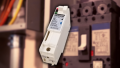
Figure 2. A typical Solid State Relay. This relay is designed for 3.5-32 volts input, which is fairly normal, but should only be used with a DC load device, up to 60 volts at 3 amps of current.
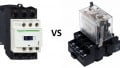
There are two variants of the relay. The electromechanical version has existed since the very beginning of control electronics. The newer solid state relay operates with semiconductor technologies, usually based on silicon transistor variations.
Although they can accomplish many of the same tasks, the operating principles are so vastly different that it requires a contrast of what sets the two devices apart from each other.
Operating Theory of the Mechanical Relay
The mechanical relay uses a coil of wire generating a magnetic field using the principle of inductance. The magnetic field attracts a swinging arm to engage the contacts.
The solid-state relay input energizes an internally constructed LED, with an appropriate current-limiting resistor integrated inside. The light from the LED energizes a photo-responsive amplifier on the contact side.
Control Coil Voltage Ratings
The mechanical relay uses a specifically rated AC or DC voltage for the coil input, and it can vary from 3.3 V on computer circuits up to 24 V in DC, or from 24 V up to 120 V or higher AC supplies. Each relay operates with one single voltage only. To use two voltages means you must have two separate models of the relay.
The solid-state relay accepts DC inputs, usually in a wide range of inputs. Anywhere from 3 to 32 Volts is usually a common range, and a single SSR may be installed for any control voltage within this range.
Output Contacts (Poles and Throws)
The mechanical relay always includes one or more sets of physical contacts that open or close as the magnetic field is applied from the coil.
The most common is for each contact set to include a common power terminal, and separate terminals for a normally open (NO) contact, as well as a normally closed (NC).
This is called double-throw. There may be one, two, or four contact sets (called Poles), but other variations can be found. This leads to naming conventions such as single-pole double-throw (SPDT), or double-pole double-throw (DPDT), etc.

Figure 3. The four copper tabs on this larger mechanical relay display the construction of a 4-Pole Double-Throw (4PDT) relay model.
The solid-state relay does not have physical contact sets, only a transistor variant (either a silicon-controlled rectifier (SCR), or similar TRIAC, etc.). Most SSRs only include one single contact set, and this contact only contains one single normally open (NO) circuit. This would simply be called an SPST construction.
Contact Voltage Limits of Mechanical Relays
Mechanical relays are constructed like switches, so they can handle either AC or DC. Care must be taken to never exceed maximum voltage ratings or dangerous arcs can occur, and for each voltage, only certain current limits may be used to prevent dangerous energy releases upon closing and opening.
Solid-state relays do not have the problem with arcs jumping over an open contact like the mechanical types. Instead, these sensitive semiconductor devices will be ruined and burned if an excessive voltage is applied to the material, so regardless, you must pay attention to the rated voltage.
They will also be damaged with excess current, since solid-state devices cannot physically disconnect. There will always become small resistance, which generates heat. For best performance, try to find a device with the smallest “On-State Resistance” value possible.
Load Circuit Polarity of Solid State Relays
An important fact about the SSR construction is that on the output side, it may consist of either a high-power Field-Effect Transistor (FET) or the TRIAC. Either device may be switched using photo-sensitive components, but each has a specific purpose.
The FET is designed for DC loads only, it will not allow an AC load to activate. Likewise for the TRIAC, since these devices operate using AC waves, it will only properly activate and deactivate an AC load.
If using a solid-state relay, look at the contact side, and pay attention to the voltage, the current, and also the important point of either AC or DC load switching.

Figure 4. A printed circuit board with an array of solid-state relays. Each relay is designed to switch an AC load (indicated with the ~ symbol), up to 240 volts with no more than 2.0 amps of current.
Mechanical and solid-state relays are all designed with one goal in mind - the input voltage activates the output contacts. The methods by which they operate are very different, and therefore one may be superior to the other for certain scenarios.
A separate article will investigate which situations may be best served by a mechanical or a solid-state relay.
Love relays? So do we! Check out our collection of relay content:
- How to Troubleshoot Mechanical Relays
- Info Byte: What’s the Reason Behind Relay Terminal Numbering?
- Info Byte: Preventing Relay Burnout with Flyback Diodes
- Understanding the Differences Between Protection Relays vs Control Relays
- Info Byte: The Mystery of Ice Cube Relays–Coil Polarity
- I/O Module Debate: Digital Output or Relay Output?
- Contactors versus Relays - Differences and Applications
All images used courtesy of the author.