 Facebook
 Google
 GitHub
 Linkedin
I/O Module Debate: Transistor vs. Relay Output?
When selecting the right module for the right load, be sure to understand how the load resistance will affect the voltage and current of the output module terminals.
It should be simple.
Input device information comes into an input module on a controller, and output modules send signals to output devices from the controller.
But that’s where the simplicity ends.
AC or DC? Sourcing or sinking? Discrete or analog? Digital or relay? These are just a few of the questions facing a design engineer or technician, and the answers depend on the field equipment specifications.
Recently, I was faced with a challenge that, after many years of working with PLCs, I still had not seen until this past week.
Check out our exclusive ebook: The Complete Guide to Relays!
The Problem - Output Stuck ON
I was connecting some external relay module boards to the output terminals of a PLC system. This output module was a DC 24 volt output, and the relay boards had rated a coil voltage of 24 volts as well—not an unusual scenario.

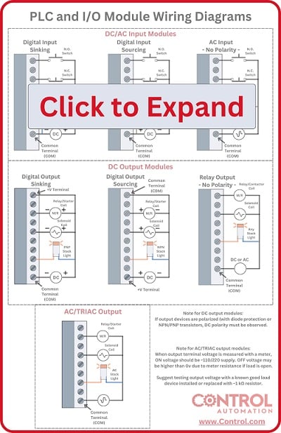
Figure 1. PLC I/O modules are flexible but can have many hidden surprises when connected to various load devices. Image used courtesy of Canva
The purpose was to interface a signal to a small microcontroller so the 24 volt PLC output would be far too much for the 5 volt tolerant controller GPIO. Buying the small relay boards was more cost effective than a new relay output module for the PLC or purchasing 24 volt ice cube relays.
After wiring the boards to the PLC output module and verifying the logic, I found that the relay board would energize but not all would fully de-energize.
The Symptoms
A small LED indicated the presence input voltage to the relay board and this gave some information.
- When the PLC output was energized, the LED was brightly lit and the relay distinctly energized with a ‘click’.
- When the PLC output was de-energized, the indicator LED on the relay board would grow dim, and on some modules, would turn off entirely. In many cases, the relay remained energized.
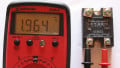
- Measuring the voltage on the relay input displayed 23.8 volts when ‘on’ and 2.2 volts when ‘off’—the latter of which should have been sufficient to de-energize the relay.
Further datasheet research indicated that the relay board module had an opto-coupled isolation between the input terminal to the actual relay coil.

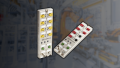
Figure 2. The 24 volt relay board, the tricky subject of today’s challenge. Image used courtesy of Amazon
Since these optocoupler devices are quite common for isolation in industrial devices, I wanted to learn more and figure out why this situation did not function as intended.
Many of you may already be correctly predicting the cause of this failure.
The Diagnosis - Wrong Module Type
In optically coupled devices, a small amount of power is required to drive an IR LED inside a small, sealed integrated circuit (IC) package on the board. The light from that LED strikes a phototransistor which then acts as a valve, allowing more current to flow through the relay coil in an external circuit.
In order to forward-bias an IR LED, it requires a small voltage–smaller than for most visible color LEDs. A value of less than 2 volts is usually more than enough.
With this knowledge, it was now clear that the measured voltage of 2.2 volts from the output module was enough to turn the LED on, even when the output terminal was logically de-energized.
The IR LED inside the optocoupler required less voltage than the visible red indicator LED. This means that, although the in-line resistor was allowing only barely enough power for the red LED to glow, the IR LED deep inside was still glowing.
This problem is encountered in many solid-state input devices, such as solid-state relays (SSRs) and any components with an amplified input using transistors or operational amplifiers. In such cases, even a small voltage can be amplified to drive a large load. Bipolar transistors (BJTs) only need about 0.7 volts to begin conducting, and field effect transistors (FETs) may be less than 0.5 volts.
This problem may have been encountered with an opto-coupler, but obviously, this diagnosis is important to remember if you ever plan to interface a PLC with a solid state device.
The Solutions
1) Choose the Correct Output Module Type.
Digital (transistor-based) output modules always have some amount of leakage current, and therefore they develop a voltage in the presence of a functioning output circuit. In order to avoid this, a relay output module provides a complete absence of leakage current and voltage when ‘off’.
The reason for this is quite obvious, but it puts the next solution into a better context. When a relay contact opens, it has nearly infinite resistance. No current can pass through, and no load device will ever encounter a voltage drop until those contacts close.
The downside to using a relay output module is the limited switching speed. If using inductive DC loads, a relay module may also experience premature failure if you do not protect the load coils with diodes from the flyback voltage.

Figure 3. A module specification sheet illustrating the maximum rated output leakage current (in the off state)
2) Verify the Specifications of the Output Module
Unlike relay modules, digital output modules have a resistance of less than infinity when de-energized, though the resistance is still quite high. High resistance leads to a low leakage current rated on the module datasheet.
For most output devices, like a solenoid or contactor, that leakage current won’t even come close to energizing the device. However, if the output device only needs a small amount of operating current, it may remain energized.
This is just like the opto-coupled relay board in our scenario.
Explanation - Ohm’s Law. Again.
In any output module, the circuit can be represented as a series of two resistors: the output module and the load device.
Relay Module Output Resistance
In a relay output, the resistance of the module is either 0 Ohms (on) or nearly infinite Ohms (off). This means that the voltage remaining for the load device is either full supply voltage, or 0 volts, regardless of the load’s resistance.

Figure 4. Simplified schematic of a relay module, represented as an N.O. switch, paired with any size load device.
Digital Module Output Resistance
In the case of a digital transistor output (and AC triac output modules are included), the resistance is very low when ‘on’ and very high when ‘off’. Since it must be considered a voltage divider, the resistance of the load is a significant player.

Figure 5. I/O module with high resistance, paired in series with a low-resistance load on the left, and a higher-resistance load on the right.
If the resistance of the load is low (like a solenoid), the high ‘off’ resistance of the module, paired with the low resistance of the load, will result in a very low voltage for the load, as shown on the left in Figure 5. This voltage is too low to allow sufficient current–which is also a function of the resistance.
In a high resistance load, such as our optocoupler, there is now a high ‘off’ resistance in the module, paired with a high resistance of the load, and the voltage will be significantly higher, as shown on the right Figure 5.
Since the voltage is higher and the current needed is quite low, it might just remain energized.
Even remaining energized when the output module is turned off.
Love relays? So do we! Check out our whole collection of relay content:
- Differences Between Electromechanical and Solid State Relays
- How to Troubleshoot Mechanical Relays
- Info Byte: What’s the Reason Behind Relay Terminal Numbering?
- Info Byte: Preventing Relay Burnout with Flyback Diodes
- Understanding the Differences Between Protection Relays vs Control Relays
- Info Byte: The Mystery of Ice Cube Relays–Coil Polarity
- Contactors versus Relays - Differences and Applications


Thanks for sharing your thoughts on this subject. I had similar problems in the past. When you see it the first time: you switch the IO signal off and the relay stays on….you think that some weird black-magic is going on…..
Add a Pull Down / or pull up resitor to take care of that probelm
you measured 2.2 volts with the output off but that occured with a meter with 10 megohm impedence. Adding a 2.2K resistor connected to 0v will pull the voltage down low enough turn off your opto coupler.
Also “The downside to using a relay output module is the limited switching speed. If using inductive DC loads, a relay module may also experience premature failure if you do not protect the load coils with diodes from the flyback voltage.”
The coil of the relay module is controlled by the PLC and will not fail because of load current.
The contacts of the output module may arc but they are a lot more tolerant of inductive loads than typical PNP or NPN outputs on a PLC
The real downside to relay output modules is the cost. They cost more per output, they do not have the densisty of transistor outputs which uses more panel space. Switching speed esp. with an inducitve load is not usually an issue. Depending on the card layout they are good when different voltages or sources of voltages need to be used. They also typically have higher current ratings than transistor outputs.